Introduction
All Maple Systems HMIs programmed with EBPro (EasyBuilder Pro), including every cMT X Series and cMT Series model, are compatible with a Yaskawa Electric MP Series – Extension (Ethernet). Configure your Controller and HMI/cMT with the following parameters to establish reliable communication.
Protocol: Ethernet (UDP)
HMI Settings
| Parameters | Recommended | Options | Notes |
|---|---|---|---|
| PLC type | YASKAWA MP Series – Extension (Ethernet) | ||
| PLC I/F | Ethernet (UDP) | ||
| Port no. | 10000 | ||
| PLC sta. no. | 1 |
PLC Settings
PLC Factory Communication Parameter Settings
| Item | Set |
|---|---|
| IP Address | 192.168.1.1 |
| Subnet Mask | 255.255.255.0 |
| Gateway IP Address | 0.0.0.0 |
| System Port No. | 10000 (UDP) |
| TCP Zero Window Timer Value | 3 (s) |
| TCP Retry Time | 500 (ms) |
| TCP Close Time | 60 (s) |
| IP Assemble Time | 30 (s) |
| Max. Packet Length | 1500 (bytes) |
Setting Steps
Set the IP address for the PLC.
In MPE720, open the Communications Setting dialog. Set Communication port to2 : Ethernet (IP:192.168.1.10)and confirm the IP address field shows192.168.1.1.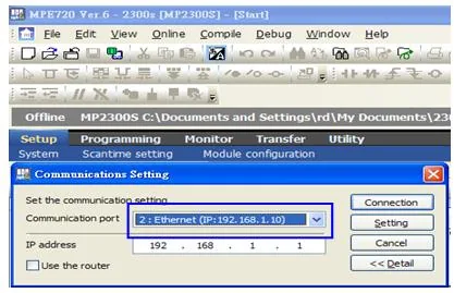
Open the communication parameter settings.
In the Setup menu, click Module configuration.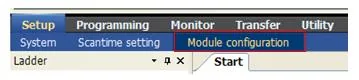
Select the 218IFA module for Ethernet parameter settings.
In the Module Details panel, right-click slot 2 and select218IFAfrom the context menu to configure the Ethernet transmission parameters. The 218IFA supports 100M Ethernet.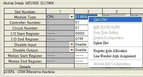
Configure Ethernet transmission parameters. The PLC IP address must be unique on the network.
In the 218IFA Transmission Parameters tab, enter the IP address, subnet mask, gateway IP, and message communication settings. Set Local Port to10000, Protocol Type toUDP, and Code toExtended MEMOBUS. The PLC IP address cannot be duplicated on the network.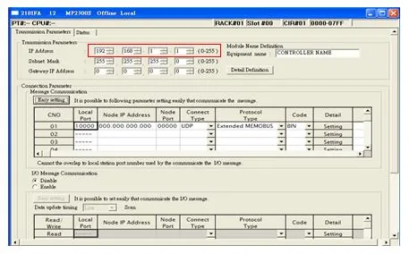
Download the communication parameters to the PLC and restart the controller.
Use Transfer u0026gt; Save to flash to write the parameters to the controller. The Transfer Program – Save to Flash dialog confirms the target asMP2400 (Ethernet(IP) IP192.168.1.1). Click Start, then restart the PLC after the transfer completes.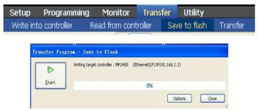
HMI Configuration Steps
Select Ethernet for PLC I/F.
In EBPro, open Device Properties for the YASKAWA MP Series Ethernet (Extension) device. Set PLC I/F toEthernet.Enable UDP.
Check the Use UDP (User Datagram Protocol) checkbox.Set the PLC IP address and port number.
Enter the PLC IP address and set the port to10000(the default). Click OK to save.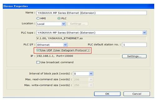
Device Address
| Bit/Word | Device type | Format | Range | Memo |
|---|---|---|---|---|
| B | SB | DDDDh | 0 ~ 8191f | |
| B | IB | HHHHh | 0 ~ fffff | |
| B | OB | HHHHh | 0 ~ fffff | |
| B | MB | DDDDDh | 0 ~ 65534f | |
| W | SW | DDDD | 0 ~ 8191 | |
| W | IW | HHHH | 0 ~ ffff | |
| W | OW | HHHH | 0 ~ ffff | |
| W | MW | DDDDD | 0 ~ 65534 | |
| DW | ML | DDDDD | 0 ~ 65534 |
Wiring Diagram
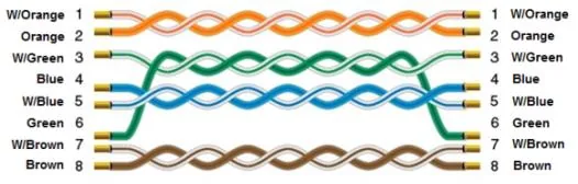
NOTE: Connect the HMI to the Yaskawa MP Series PLC using a standard Ethernet straight-through cable.
The diagram below shows the Ethernet cable wiring.