Introduction
All Maple Systems HMIs programmed with EBPro (EasyBuilder Pro), including every cMT X Series and cMT Series model, are compatible with Maple Systems Remote IO (CANopen). Configure your Controller and HMI/cMT with the following parameters to establish reliable communication.
Supported series: Maple Systems Remote IO (iR-COP)
HMI Setting
| Parameters | Recommended | Options | Notes |
|---|---|---|---|
| PLC type | Maple Systems Remote IO (CANopen) | ||
| Baud rate | 250K | 10K~1M | |
| Online simulator | NO | ||
| Extend address mode | NO |
Device Setting
Launch EBPro (EasyBuilder Pro) and add the driver
Launch EBPro (EasyBuilder Pro) and add the Maple Systems Remote I/O (CANopen) driver into the device list. Click Device Manager to configure the CANopen device and addresses.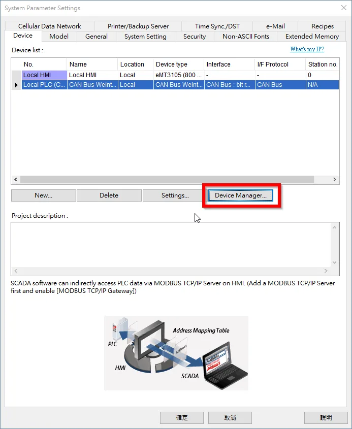
View the default device in Device Manager
In the Device Manager window, a Maple Systems Remote I/O CANopen device (iR-COP) is found by default.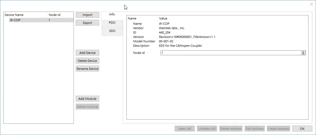
Use the buttons on the left side
Clicking the buttons on the left side of the Device Manager window performs the following actions:
Import: Import a predefined
.wtcofile into the device list. The current device list will be overwritten by the imported list.Export: Export the current setting as a
.wtcofile for future use. Add Device: Add a new Maple Systems Remote I/O CANopen device.Delete Device: Delete the selected Maple Systems Remote I/O CANopen device.
Rename Device: Change the device name.
Add Module: Adding modules will show address information correctly. Delete Module: Delete the selected module.
Configure device tags using the Info, PDO, and SDO tabs
Select a device to access the Info, PDO, and SDO tabs on the right side of the Device Manager window.
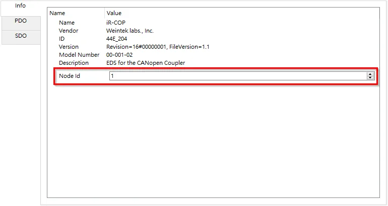
Info — Displays device information. Node ID can be changed within 1–127.
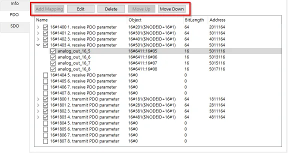
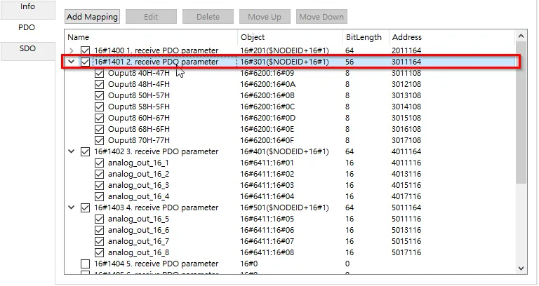
PDO (Process Data Object) — This tab displays TxPDO and RxPDO Mapping for editing. Changes in the PDO tab will not be updated to the Remote I/O. Editing PDO Mapping here ensures the correct bit length when importing addresses to the HMI, and that the displayed address names on the HMI match those used in CANopen.
The five buttons at the top of the PDO tab can:
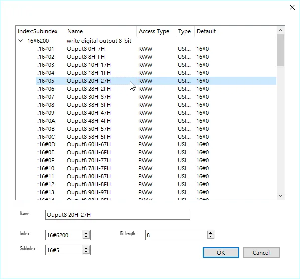
Add Mapping: When the PDO object’s bit length is less than 64, the user can add a PDO Mapping into the list and select the source of the Mapping Object.
Edit: Change the source of the selected Mapping Object.
Delete: Delete the selected Mapping Object.
Move Up: Move the selected Mapping Object one row upward.
Move Down: Move the selected Mapping Object one row downward.
SDO (Service Data Object) — Displays all items in the Object Dictionary.
Select and define addresses in the SDO tab
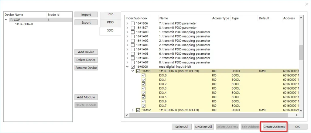
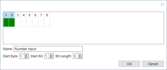
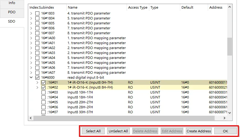
Users can define the address range of existing items. For example, to add a user-defined address range under item
[6000]read digital input 8-bit #01 in the SDO tab, select the item in the index tree and click Create Address.A dialog box appears for defining the address range. Using the settings below will add a Number Input tag under item
[6000]read digital input 8-bit #01. The tag will use bits 1–2 of the item as its value. That is, if the value in the item is 15, the value in the tag will be 3.The buttons at the bottom of both the SDO and PDO tabs can:
Select All: Select all items.
Unselect All: Unselect all items.
Delete Address: Delete a user-defined address.
Edit Address: Edit a user-defined address.
Create Address: Create a user-defined address.
OK: Import addresses.
Device Address
| Bit/Word | Device type | Format | Range | Memo |
|---|---|---|---|---|
| W | SDO_DATA | HHHIIIISSBbNN | 1101~FFFFFFFFFFFF8801 | H: CAN ID I: Index S: SubIndex B: Byte position (1~8) b: bit start position (1~8) NN: bit no. (1~64) |
| W | PDO_DATA | HHHHHHHHBbNN | 1101~1FFFFFFFFFFF8801 | H: CAN ID B: Byte position (1~8) b: bit start position (1~8) NN: bit no. (1~64) |
| B | PDO_DATA_Bit | HHHHHHHHBb | 11~1FFFFFFFFF88 | H: CAN ID B: Byte position (1~8) b: bit start position (1~8) |
| B | SDO_DATA_Bit | HHHIIIISSBb | 11~FFFFFFFFFFFFF88 | H: CAN ID I: Index S: SubIndex B: Byte position (1~8) b: bit start position (1~8) |
| B | SEND_NMT | D | 0 | Set on sends NMT Command; automatically returns to off. |
Wiring Diagram
Diagram 1 — CAN BUS
NOTE: The serial port pin assignments may vary between HMI models.
| HMI | Direction | PLC |
|---|---|---|
| Pin assignments | CAN Bus Device | |
| CAN_L | ↔ (bidirectional) | CAN_L |
| CAN_H | ↔ (bidirectional) | CAN_H |
| GND | ↔ (bidirectional) | GND |
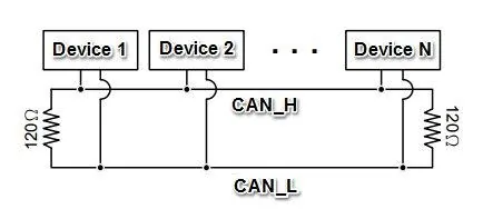
To minimize signal reflection on the CAN bus network, termination resistors should be installed at both ends of the network, as shown in the following figure. (eMT3070A has a built-in termination resistor and does not require one.)