
Introduction
All Maple Systems HMIs programmed with EBPro (EasyBuilder Pro), including every cMT X Series and cMT Series model, are compatible with Panasonic FP/KW Series. Configure your Controller and HMI/cMT with the following parameters to establish reliable communication.
Supported Series: NAIS (Matsushita) FP/KW series include FP-X, FP-XH, FP-Σ, FP0, FP1, FP2, FP2SH, FP10SH, FP7
Website: pewa.panasonic.com
HMI Settings
| Parameters | Recommended | Options | Notes |
|---|---|---|---|
| PLC type | Panasonic FP/KW | ||
| PLC I/F | RS232 | RS232/RS485 | |
| Baud rate | 9600 | 9600, 19200, 38400, 57600, 115200 | |
| Data bits | 8 | 7 or 8 | |
| Parity | Odd | Even, Odd, None | |
| Stop bits | 1 | 1 or 2 | |
| PLC sta. no. | 1 | 1–32 | Must match the PLC port setting. FP3 must set to 0. |
| Protocol | Multi-read | Multi-read / Single read |
- Supports communications between HMI and PLC in pass-through mode.
- Set
LW-9903to2to enhance the speed of download/upload PLC program in pass-through mode. - When using pass-through, the driver will stop communication between HMI and PLC.
PLC Settings
Operating mode setting: MEWTOCOL-COM
Device Address
| Bit/Word | Device type | Format | Range | Memo |
|---|---|---|---|---|
| B | X | DDDDh | 0 ~ 9999f | Input (X) |
| B | Y | DDDDh | 0 ~ 9999f | Output (Y) |
| B | R | DDDDh | 0 ~ 9999f | Internal Relay (R) |
| B | L | DDDD | 0 ~ 9999 | Link Relay (L) |
| B | L_Bit | DDDDh | 0 ~ 9999f | |
| B | T | DDDD | 0 ~ 9999 | Timer (T) |
| B | C | DDDD | 0 ~ 9999 | Counter (C) |
| W | SV | DDDD | 0 ~ 9999 | Timer/Counter Set Value |
| W | EV | DDDDD | 0 ~ 65535 | Timer/Counter Elapse Value |
| W | DT | DDDDD | 0 ~ 99999 | Data Register (DT) |
| W | LD | DDDD | 0 ~ 8447 | Link Register (LD) |
| W | WX | DDDD | 0 ~ 9999 | Input (WX) (read only) |
| W | WY | DDDD | 0 ~ 9999 | Output (WY) |
| W | WR | DDDD | 0 ~ 9999 | Internal Relay (WR) |
| W | WL | DDDD | 0 ~ 9999 | Link Relay (WL) |
| W | FL | DDDDD | 0 ~ 99999 | File Register (FL) |
| W | DT_String | DDDDD | 0 ~ 99999 | *Note 1 |
Note 1: The address range depends on the actual support range of each PLC model.
Data table for character strings stores the character string size, the number of characters, and the character data. The example below specifies:
- Character string size: 6
- Number of characters: 6
- Character data: “ABCDEF”
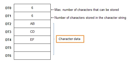
DT_String starts reading from the character data field. On write, it automatically fills in character string size and number of characters. It is not recommended to use DT_String in data sampling.
Note 2: The address range depends on the actual support range of each PLC model.
Wiring Diagrams
NOTE: The serial port pin assignments may vary between HMI models.
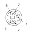
Diagram 1: RS-232 (FP0, FP2, FP2SH, FPM CPU: 9P D-Sub to 5P Mini-DIN)
The following is the view from the soldering point of a connector.
| HMI | Direction | PLC |
|---|---|---|
| Pin assignments | RS232 5P Mini-DIN Male | |
| Rx | ↔ (bidirectional) | 2 TXD |
| Tx | ↔ (bidirectional) | 3 RXD |
| GND | ↔ (bidirectional) | 1 GND |
Diagram 2: RS-232 (FP0 CPU: 9P D-Sub to 3P Terminal)
| HMI | Direction | PLC |
|---|---|---|
| Pin assignments | RS232 3P Terminal | |
| Rx | ↔ (bidirectional) | S |
| Tx | ↔ (bidirectional) | R |
| GND | ↔ (bidirectional) | G |
Diagram 3: RS-232 (RS232 9P D-Sub Male)
| HMI | Direction | PLC |
|---|---|---|
| Pin assignments | RS232 9P D-Sub Male | |
| Rx | ↔ (bidirectional) | 2 TXD |
| Tx | ↔ (bidirectional) | 3 RXD |
| GND | ↔ (bidirectional) | 7 GND |
| ↕︎ (tie) | 4 RTS 5 CTS | |
| ↕︎ (tie) | 8 CD 9 ER |
Diagram 4: RS-485 4W (FP1 CPU: 9P D-Sub to 8P MiniDIN)
The following is the view from the soldering point of a connector.

| HMI | Direction | PLC |
|---|---|---|
| Pin assignments | RS485 4W 8P Hirose Female socket | |
| Rx- | ↔ (bidirectional) | 2 TXDA |
| RX+ | ↔ (bidirectional) | 5 TXDB |
| Tx- | ↔ (bidirectional) | 3 RXDA |
| Tx+ | ↔ (bidirectional) | 6 RXDB |
| GND | ↔ (bidirectional) | 1 GND |
Diagram 5: RS-485 4W (FP3 CPU: 9P D-Sub to 15P D-Sub)
| HMI | Direction | PLC |
|---|---|---|
| Pin assignments | RS485 4W 15P D-Sub Male | |
| Rx- | ↔ (bidirectional) | 9 TXDA |
| RX+ | ↔ (bidirectional) | 2 TXDB |
| Tx- | ↔ (bidirectional) | 10 RXDA |
| Tx+ | ↔ (bidirectional) | 3 RXDB |
| GND | ↔ (bidirectional) | 7 GND |
| ↕︎ (tie) | 4 RTS+ 5 CTS+ | |
| ↕︎ (tie) | 11 RTS- 12 CTS- |