
Introduction
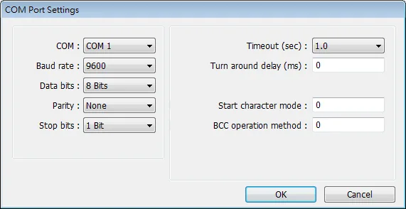
All Maple Systems HMIs programmed with EBPro (EasyBuilder Pro), including every cMT X Series and cMT Series model, are compatible with Shimaden MR13/FP93. Configure your Controller and HMI/cMT with the following parameters to establish reliable communication.
Supported Series: MR13, FP93 devices
Website: http://www.shimaden.co.jp
HMI Setting
| Parameters | Recommended | Options | Notes |
|---|---|---|---|
| PLC type | SHIMADEN MR13/FP93 | ||
| PLC I/F | RS485 2W | ||
| Baud rate | 9600 | 1200–19200 | |
| Data bits | 7 | 7 or 8 | |
| Parity | E | None/Even | |
| Stop bits | 1 | 1 | |
| PLC sta. no. | 1 | 1–255 | |
| Start Character Mode | Select 3: @_:_CR | 0, 1: STX_ETX_CR 2: STX_ETX_CR LF 3: @_:_CR | For FP93, select 0, 1 |
| BCC Operation Method | Select 3: XOR | 0, 1: Addition 2: Addition +2’s complement 3: XOR 4: None |
NOTE: Address 018C is a communication control register. Only when it is set to 1 can this register be allowed to write to other registers.
Device Address
| Bit/Word | Device | Format | Range | Memo |
|---|---|---|---|---|
| W | Channel 1 | HHHH | 0 ~ ffff | Read/Write 1st Channel Register |
| W | Channel 2 | HHHH | 0 ~ ffff | Read/Write 2nd Channel Register |
| W | Channel 3 | HHHH | 0 ~ ffff | Read/Write 3rd Channel Register |
MR13 Communication Parameter Settings
| Data Address (hex) | Parameter | Details of Parameter | R/W |
|---|---|---|---|
0100 | PV Value | Within measuring range | R |
0101 | E_SV Execution SV Value | Within setting range | R |
0102 | OUT Control Output Value | Within range 0.0~100.0% | R |
0103 | Reserved | ||
0104 | Action Flag | (See detailed explanation below.) | R |
0105 | Event Output Flag | (See detailed explanation below.) | R |
0106 | Reserved | ||
0107 | Reserved | ||
0108 | REM Value | Within setting range | R |
0109 | Reserved | ||
010A | Reserved | ||
010B | DI Input State Flag | (See detailed explanation below.) | R |
0111 | RANGE | Refer to the measuring range code list. | R |
0112 | Reserved | ||
0113 | DP Decimal Point | Position of decimal point (0: Without decimal point, 1: With decimal point) | R |
0114 | PV Sc_L Lower Limit | For Linear Input: -1999~9999 unit. For Thermocouple and RTD Input: Measuring range to be displayed. | R |
0115 | PV Sc_H Higher Limit | For Thermocouple and RTD Input: Measuring range to be displayed. | R |
0120 | E_PRG Program Action Flag | R | |
0121 | Reserved | ||
0122 | Reserved | ||
0123 | E_PRT | The number of execution patterns (When program is reset, value=7FFEH) | R |
0124 | E_STP | Execution step number (When program is reset, value=7FFEH) | R |
0125 | E_TIM | Remaining time of execution step (When program is reset, value=7FFEH) | R |
0126 | E_PID | Execution PID number (When program is reset, value=7FFEH) | R |
0184 | AT Auto Tuning | 0: No execution, 1: Execution | W |
018C | Operation | 0: Local, 1: COM | W |
0190 | PROG RUN/RST Program Run/Reset | 0: RST, 1: RUN (Writing is possible only in CH1) | W |
0191 | PROG HLD Program Hold | 0: Release, 1: HLD (Writing is possible only in CH1) | W |
0300 | SV | Local SV Value, within set value limiter | R/W |
030A | SV Limt_L Lower Limit | Within measuring range, on condition that SV Limt_L < SV Limt_H | R/W |
030B | SV Limt_H Higher Limit | Within measuring range, on condition that SV Limt_L < SV Limt_H | R/W |
0314 | REM SC_L | Within measuring range, on condition that REM SC_L ≠ REM SC_H | R/W |
0315 | REM SC_H | Within measuring range, on condition that REM SC_L ≠ REM SC_H | R/W |
0316 | REM Bias | Range: -1999~5000 unit | R/W |
0317 | REM Filt | Range: 0~100 seconds | R/W |
031A | REM-CH | Remote channel assignment: 0: OFF, 1: CH1, 2: CH2, 3: CH3 | R/W |
0320 | SV Follow SW | CH2 & CH3 SV follow setting flag: 1: Follow, 0: No | R/W |
0321 | SV Follow | Follow type deviation SV set value: -1999~5000 unit | R/W |
0400 | FIX P | Control Output Proportional Band. Range: 0.0~999.9% (0.0: OFF) | R/W |
0401 | FIX I | Control Output Integral Time. Range: 0~6000 seconds (0.0: OFF) | R/W |
0402 | FIX D | Control Output Derivative Time. Range: 0~3600 seconds (0.0: OFF) | R/W |
0403 | FIX MR | Manual Reset. Range: -50.0~50.0% | R/W |
0404 | FIX DF | Hysteresis. Range: 1~999 unit | R/W |
0405 | FIX OUT Limt_L | Control Output Lower Limit Output Limiter. Range: 0.0~99.9% | R/W |
0406 | FIX OUT Limt_H | Control Output Higher Limit Output Limiter. Range: 0.1~100.0% | R/W |
0407 | FIX SF | Control Output Target Value Function. Range: OFF, 0.01~1.00 | R/W |
0408 | Prog P1 | PROG mode PB1. Range: 0.0~999.9% (0.0: OFF) | R/W |
0409 | Prog I1 | PROG mode IT1. Range: 0~6000 seconds (0.0: OFF) | R/W |
040A | Prog D1 | PROG mode DT1. Range: 0~3600 seconds (0.0: OFF) | R/W |
040B | Prog MR1 | PROG mode MR1. Range: -50.0~50.0% | R/W |
040C | Prog DF1 | PROG mode DF1. Range: 1~999 unit | R/W |
040D | Prog O_Lmt_L1 | PROG mode lower limit side output limiter 1. Range: 0.0~99.9% | R/W |
040E | Prog O_Lmt_H1 | PROG mode higher limit side output limiter 1. Range: 0.1~100.0% | R/W |
040F | Prog SF1 | PROG mode target value function 1. Range: OFF, 0.01~1.00 | R/W |
0410 | Prog P2 | PROG mode PB2. Range: 0.0~999.9% (0.0: OFF) | R/W |
0411 | Prog I2 | PROG mode IT2. Range: 0~6000 seconds (0.0: OFF) | R/W |
0412 | Prog D2 | PROG mode DT2. Range: 0~3600 seconds (0.0: OFF) | R/W |
0413 | Prog MR2 | PROG mode MR2. Range: -50.0~50.0% | R/W |
0414 | Prog DF2 | PROG mode DF2. Range: 1~999 unit | R/W |
0415 | Prog O_Lmt_L2 | PROG mode lower limit side output limiter 2. Range: 0.0~99.9% | R/W |
0416 | Prog O_Lmt_H2 | PROG mode higher limit side output limiter 2. Range: 0.1~100.0% | R/W |
0417 | Prog SF2 | PROG mode target value function 2. Range: OFF, 0.01~1.00 | R/W |
0418 | Prog P3 | PROG mode PB3. Range: 0.0~999.9% (0.0: OFF) | R/W |
0419 | Prog I3 | PROG mode IT3. Range: 0~6000 seconds (0.0: OFF) | R/W |
041A | Prog D3 | PROG mode DT3. Range: 0~3600 seconds (0.0: OFF) | R/W |
041B | Prog MR3 | PROG mode MR3. Range: -50.0~50.0% | R/W |
041C | Prog DF3 | PROG mode DF3. Range: 1~999 unit | R/W |
041D | Prog O_Lmt_L3 | PROG mode lower limit side output limiter 3. Range: 0.0~99.9% | R/W |
041E | Prog O_Lmt_H3 | PROG mode higher limit side output limiter 3. Range: 0.1~100.0% | R/W |
041F | Prog SF3 | PROG mode target value function 3. Range: OFF, 0.01~1.00 | R/W |
0500 | EV1_MODE | 0: Not assigned, 1: Higher limit deviation value, 2: Lower limit deviation value, 3: Out of range between higher & lower limits, 4: Within range between higher & lower limits, 5: Higher limit absolute value, 6: Lower limit absolute value, 7: Scaleover, 8: Program RUN, 9: Program END, 10: Program STEP. Only when Subaddress=EV1_CH. | R/W |
0501 | EV1 Set Point | 1. Higher limit deviation value alarm: 0~1999 unit. 2. Lower limit deviation value alarm: 0~-1999 unit. 3. Out of range between higher & lower limits value alarm: 0~1999 unit. 4. Within range between higher and lower limits value alarm: 0~1999 unit. 5. Higher limit absolute value alarm: Within measuring range. 6. Lower limit absolute value alarm: Within measuring range. Only when Subaddress=EV1_CH. | R/W |
0502 | EV1 Diffrnt | Alarm hysteresis. Range: 1~999 unit. Only when Subaddress=EV1_CH. | R/W |
0503 | EV1 Inhibit | Alarm stand by. Range: 1~4. Only when Subaddress=EV1_CH. | R/W |
0504 | EV1 Delay | Alarm delay time. Range: 0~9999 seconds. Only when Subaddress=EV1_CH. | R/W |
0506 | EV1_CH | Channel number setting: 1: CH1, 2: CH2, 3: CH3 | R/W |
0510 | EV2_MODE | 0: Not assigned, 1: Higher limit deviation value, 2: Lower limit deviation value, 3: Out of range between higher & lower limits, 4: Within range between higher & lower limits, 5: Higher limit absolute value, 6: Lower limit absolute value, 7: Scaleover, 8: Program RUN, 9: Program END, 10: Program STEP. Only when Subaddress=EV2_CH. | R/W |
0511 | EV2 Set Point | 1. Higher limit deviation value alarm: 0~1999 unit. 2. Lower limit deviation value alarm: 0~-1999 unit. 3. Out of range between higher & lower limits value alarm: 0~1999 unit. 4. Within range between higher and lower limits value alarm: 0~1999 unit. 5. Higher limit absolute value alarm: Within measuring range. 6. Lower limit absolute value alarm: Within measuring range. Only when Subaddress=EV2_CH. | R/W |
0512 | EV2 Diffrnt | Alarm hysteresis. Range: 1~999 unit. Only when Subaddress=EV2_CH. | R/W |
0513 | EV2 Inhibit | Alarm stand by. Range: 1~4. Only when Subaddress=EV2_CH. | R/W |
0514 | EV2 Delay | Alarm delay time. Range: 0~9999 seconds. Only when Subaddress=EV2_CH. | R/W |
0516 | EV2_CH | Channel number setting: 1: CH1, 2: CH2, 3: CH3 | R/W |
0520 | EV3_MODE | 0: Not assigned, 1: Higher limit deviation value, 2: Lower limit deviation value, 3: Out of range between higher & lower limits, 4: Within range between higher & lower limits, 5: Higher limit absolute value, 6: Lower limit absolute value, 7: Scaleover, 8: Program RUN, 9: Program END, 10: Program STEP. Only when Subaddress=EV3_CH. | R/W |
0521 | EV3 Set Point | 1. Higher limit deviation value alarm: 0~1999 unit. 2. Lower limit deviation value alarm: 0~-1999 unit. 3. Out of range between higher & lower limits value alarm: 0~1999 unit. 4. Within range between higher and lower limits value alarm: 0~1999 unit. 5. Higher limit absolute value alarm: Within measuring range. 6. Lower limit absolute value alarm: Within measuring range. Only when Subaddress=EV3_CH. | R/W |
0522 | EV3 Diffrnt | Alarm hysteresis. Range: 1~999 unit. Only when Subaddress=EV3_CH. | R/W |
0523 | EV3 Inhibit | Alarm stand by. Range: 1~4. Only when Subaddress=EV3_CH. | R/W |
0524 | EV3 Delay | Alarm delay time. Range: 0~9999 seconds. Only when Subaddress=EV3_CH. | R/W |
0526 | EV3_CH | Channel number setting: 1: CH1, 2: CH2, 3: CH3 | R/W |
0580 | DI | DI setting flag: 0: NON, 1: FLW, 2: RUN, 3: HLD, 4: ADV | R/W |
05B0 | MEM | 1: EEP Program Memory, 0: RAM Random Memory | R/W |
0600 | Out Actn | Output characteristic setting flag: 0: Rev Act., 1: Dir Act | R/W |
0601 | Out Cyc | Control output cycle (Unit: 0.5 seconds). Range: 0.5~120.0 seconds | R/W |
0602 | Reserved | ||
0603 | SOFTSW | Soft start setting flag: 0: OFF, 1: ON | R/W |
0610 | AT Point | AT pointer. Range: 0~5000 unit | R/W |
0611 | Key Lock | 0: OFF, 1: LOCK1, 2: LOCK2, 3: LOCK3 ● When Out_Cyc is written, writing data is adjusted to 0.5 sec as one unit. ● The write command lock by keylock is the same as the screen lock. (Refer to the manual of the instrument.) ● If there is a change in EV1_CH,EV2_CH,EV3_CH, the related parameters are initialized. | R/W |
0701 | PV Bias | PV bias. Range: -1999~1999 unit | R/W |
0702 | PV Filt | PV filter. Range: 0~100 seconds | R/W |
0710 | PFLW | Setting of CH2, CH3 PV input follow: 0: OFF, 1: ON | R/W |
0711 | CH_P | Selection of CH2, CH3 PV display or not (0-0 Window): 0: Without, 1: With | R/W |
0800 | FP_MOD | Selection between FIX and PROG: 0: FIX, 1: PROG (Writing possible only in CH1) | R/W |
0801 | PV_ST | Setting of PV start: 0: OFF, 1: ON (Writing possible only in CH1) | R/W |
0882 | STP | The number of steps. Range: 1~9 (Writing possible only in CH1) | R/W |
0883 | RPT | The number of execution repetitions. Range: 1~9999 (Writing possible only in CH1) | R/W |
0884 | ST_SV | Start SV (Writing possible only in CH1) For CH1, PFLW (window 1~30), CH_P (window1-29)display- – – -.The read value is: 7FFEH, To a write command, error(0BH)is returned. | R/W |
08A0 | Step1 SV | Step No. 1 SV Value (Writing possible only in CH1) | R/W |
08A1 | Step1 Time | Step No. 1 Step Time (Writing possible only in CH1) | R/W |
08A2 | Step1 PID No | Step No. 1 PID No. | R/W |
08A3 | Reserved | ||
08A4 | Step2 SV | Step No. 2 SV Value (Writing possible only in CH1) | R/W |
08A5 | Step2 Time | Step No. 2 Step Time (Writing possible only in CH1) | R/W |
08A6 | Step2 PID No | Step No. 2 PID No. | R/W |
08A7 | Reserved | ||
08A8 | Step3 SV | Step No. 3 SV Value (Writing possible only in CH1) | R/W |
08A9 | Step3 Time | Step No. 3 Step Time (Writing possible only in CH1) | R/W |
08AA | Step3 PID No | Step No. 3 PID No. | R/W |
08AB | Reserved | ||
08AC | Step4 SV | Step No. 4 SV Value (Writing possible only in CH1) | R/W |
08AD | Step4 Time | Step No. 4 Step Time (Writing possible only in CH1) | R/W |
08AE | Step4 PID No | Step No. 4 PID No. | R/W |
08AF | Reserved | ||
08B0 | Step5 SV | Step No. 5 SV Value (Writing possible only in CH1) | R/W |
08B1 | Step5 Time | Step No. 5 Step Time (Writing possible only in CH1) | R/W |
08B2 | Step5 PID No | Step No. 5 PID No. | R/W |
08B3 | Reserved | ||
08B4 | Step6 SV | Step No. 6 SV Value (Writing possible only in CH1) | R/W |
08B5 | Step6 Time | Step No. 6 Step Time (Writing possible only in CH1) | R/W |
08B6 | Step6 PID No | Step No. 6 PID No. | R/W |
08B7 | Reserved | ||
08B8 | Step7 SV | Step No. 7 SV Value (Writing possible only in CH1) | R/W |
08B9 | Step7 Time | Step No. 7 Step Time (Writing possible only in CH1) | R/W |
08BA | Step7 PID No | Step No. 7 PID No. | R/W |
08BB | Reserved | ||
08BC | Step8 SV | Step No. 8 SV Value (Writing possible only in CH1) | R/W |
08BD | Step8 Time | Step No. 8 Step Time (Writing possible only in CH1) | R/W |
08BE | Step8 PID No | Step No. 8 PID No. | R/W |
08BF | Reserved | ||
08C0 | Step9 SV | Step No. 9 SV Value (Writing possible only in CH1) | R/W |
08C1 | Step9 Time | Step No. 9 Step Time (Writing possible only in CH1) | R/W |
08C2 | Step9 PID No | Step No. 9 PID No. | R/W |
Wiring Diagram
NOTE: The serial port pin assignments may vary between HMI models.
RS-485 2W
| HMI | Direction | PLC |
|---|---|---|
| Pin assignments | MR13/FP93 RS485 2W Terminal | |
| Data- | ↔ (bidirectional) | 25- |
| Data+ | ↔ (bidirectional) | 24+ |
| GND | ↔ (bidirectional) | 23 GND |