Introduction
All Maple Systems HMIs programmed with EBPro (EasyBuilder Pro), including every cMT X Series and cMT Series model, are compatible with IEC 60870-5-104 IEC 104 Server. Configure your Controller and HMI/cMT with the following parameters to establish reliable communication.
Protocol: IEC 60870-5-104 (IEC 104 Server mode)
HMI Settings
| Parameters | Recommended | Options | Notes |
|---|---|---|---|
| PLC type | IEC 60870-5-104 IEC 104 Server | ||
| PLC I/F | Ethernet | ||
| Port no. | 2404 | ||
| Sector | 257 | 0 ~ 65535 | *note1 |
| Timing (T3) | 10 | *note2 | |
| Timing (K) | 12 | 1 ~ 32767 | *note3 |
*note1: Only one client can be connected at a time.
*note2: When there is no data transferred from server or client, a keep-alive package will be sent at the specified interval of time.
*note3: Communication will stop when the number of not-received APDUs reaches 12.
Device Address
| Bit/Word | Device Type | Format | Range | Memo |
|---|---|---|---|---|
| B | Single Point | DDDDD | 0 ~ 255255255 | |
| B | Single Command | DDDDD | 0 ~ 255255255 | |
| W | Double Point | DDDDD | 0 ~ 255255255 | |
| W | Measured Scaled | DDDDD | 0 ~ 255255255 | |
| W | Measured Float | DDDDD | 0 ~ 255255255 | |
| W | Integrated Totals | DDDDD | 0 ~ 255255255 | |
| W | Step Position | DDDDD | 0 ~ 255255255 | |
| W | Bitstring 32bit | DDDDD | 0 ~ 255255255 | |
| W | Double Command | DDDDD | 0 ~ 255255255 | |
| W | SetPoint Scaled Command | DDDDD | 0 ~ 255255255 | |
| W | SetPoint Float Command | DDDDD | 0 ~ 255255255 | |
| W | Regulating Step Command | DDDDD | 0 ~ 255255255 | |
| W | Bitstring 32bit Command | DDDDD | 0 ~ 255255255 |
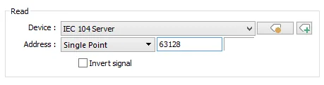
NOTE: For example: Single Point address 16256 maps to IOA Struct 000/63/128 — calculated as 16256 ÷ 256 = 63 remainder 128, so 63128 should be entered in EBPro (EasyBuilder Pro).
Application
Upper computer IEC 104 Client — HMI (IEC 104 Server) — Modbus RTU
Periodically Sends Interrogation Responses
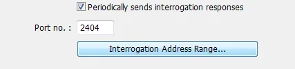
Select the Periodically sends interrogation responses checkbox and then click Interrogation Address Range to set address ranges for interrogations.
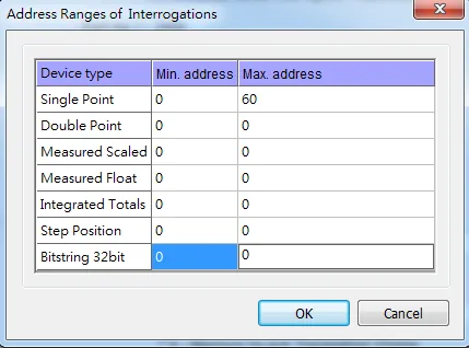
As shown above, Single Point device type in address range 0 to 60 will be sent to the Client.
NOTE: This item must be set to communicate with the IEC 60870-5-104 client for data exchange.
IEC104 Gateway
Enable and Set Address Mapping Tables

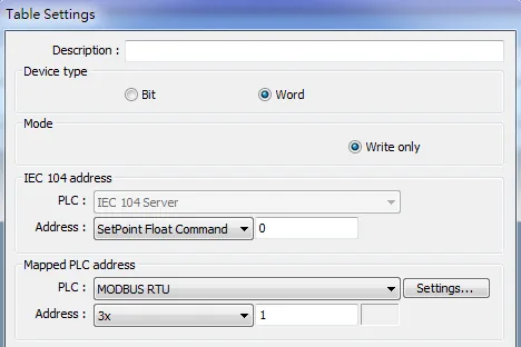
Select the Enable checkbox in the IEC104 Gateway group box. Click Address Mapping Tables to open the Table Settings window, and map IEC 104 addresses to the addresses of other devices. The applicable devices are local or Modbus PLCs.
Configure Scaling
![Table Settings Conversion and Scaling panel showing AB to BA and ABCD to CDAB byte-swap checkboxes, Dynamic scaling checkbox, and the formula [3x] = [SetPoint Float Command] × 1 + 0.](https://media.maplesystems.com/wp-content/uploads/2026/06/06-table-settings-conversion-scaling-options.webp)
Set the table size — in the example above, 12 words will be read at a time. Configure scaling options including byte-order conversion and dynamic scaling as needed.
Wiring Diagram
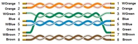
The diagram below shows the Ethernet cable wiring.