
Introduction
All Maple Systems HMIs programmed with EBPro (EasyBuilder Pro), including every cMT X Series and cMT Series model, are compatible with CD Automation Modbus RTU. Configure your Controller and HMI/cMT with the following parameters to establish reliable communication.
Supported Series: REVO-CL / REVO-M / REVO E / CD3000E / MULTIDRIVE / REVO-TC / REVO-PC
Website: http://www.cdautomation.com/
HMI Setting
| Parameters | Recommended | Options | Notes |
|---|---|---|---|
| PLC type | CD MODBUS RTU | ||
| PLC I/F | RS485 | RS232/RS485 | |
| Baud rate | 9600 | 9600~115200 | |
| Data bits | 8 | 7, 8 | |
| Parity | Even | Even, Odd, None | |
| Stop bits | 1 | 1, 2 | |
| PLC sta. no. | 1 | 0-255 | |
| Online simulator | YES | ||
| Broadcast | YES | ||
| Extend address mode | YES |

Address Range Limit: The address range of 0x, 1x, and 0x_multi_coils device types can be set.
Conversion: The 3x_Double and 4x_Double address types are added. If the [ABCD ->CDAB] check box is selected, please select 3x_Double and 4x_Double address types.
Device Address
| Bit/Word | Device type | Format | Range | Memo |
|---|---|---|---|---|
| B | 0x | DDDDD | 1 ~ 65535 | Output bit |
| B | 0x_multi_coils | DDDDD | 1 ~ 65535 | Write multiple coils |
| B | 0x_single_Bit | DDDDD | 1 ~ 65535 | |
| B | 1x | DDDDD | 1 ~ 65535 | Input bit (read only) |
| B | 1x_single_Bit | DDDDD | 1 ~ 65535 | |
| B | 3x_Bit | DDDDDdd | 100 ~ 6553515 | Input Register bit (read only) |
| B | 4x_Bit | DDDDDdd | 100 ~ 6553515 | Output Register bit |
| B | 6x_Bit | DDDDDdd | 100 ~ 6553515 | Output Register bit |
| B | 0x_1 ~ 0x_9 | DDDDD | 1 ~ 65535 | |
| B | 1x_1 ~ 1x_9 | DDDDD | 1 ~ 65535 | |
| W | 3x | DDDDD | 1 ~ 65535 | Input Register (read only) |
| W | 3x_MAX1W | DDDDD | 1 ~ 65535 | Display 32 bits *Note1 |
| DW | 3x_MAX2W | DDDDD | 1 ~ 65535 | *Note1 |
| DW | 3x_Double | DDDDD | 1 ~ 65535 | *Note2 |
| DW | 3x_QWord | DDDDD | 1 ~ 65535 | *Note2 |
| W | 4x | DDDDD | 1 ~ 65535 | Output Register |
| W | 4x_MAX1W | DDDDD | 1 ~ 65535 | Display 32 bits *Note1 |
| DW | 4x_MAX2W | DDDDD | 1 ~ 65535 | *Note1 |
| DW | 4x_Double | DDDDD | 1 ~ 65535 | *Note2 |
| DW | 4x_QWord | DDDDD | 1 ~ 65535 | *Note2 |
| W | 4x_32Bit | DDDDD | 1 ~ 65535 | Output Register *Note1 |
| W | 0x_single_coil | DDDDD | 1 ~ 65535 | *Note3 |
| DW | 5x | DDDDD | 1 ~ 65535 | 4x double word swap |
| W | 6x | DDDDD | 1 ~ 65535 | 4x single word write |
*Note1: MAX1W and 4x_32Bit reads/writes 1 word for each packet and displays a 32-bit value, whereas MAX2W reads/writes 2 words for each packet.
*Note2: Go to [System Parameter Settings] > [Device Properties] and click [Conversion] to set the data format of device types 3x, 4x, 6x, 3x_double, 4x_double, 3x_QWord, 4x_QWord.
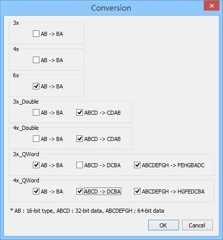
*Note3: Read/write a Bit at a time. Value 0 and 1 are used to represent ON or OFF status where 0 means set OFF and 1 means set ON.
*Note4: The number of bits to read can be set in Macro; therefore, it is recommended to use 0x address type for functions such as GetData() and SetData(), in order to increase reading speed. To read/write multiple 0x address type in macro, use 0x_multi_coils to increase write speed.
*Note5: Please assign all the addresses to Even addresses, or all to Odd addresses, in order to prevent communication failure.
*Note6: EBPro V6.03.02 or later supports 64 bits data type (cMT Series only), but please note that the address limit range is 48 bits in maximum.
5x Address Type
NOTE: Address type 5x is mapping to Hold Reg. The communication protocol of 5x is almost the same as 4x except that 5x swaps double word.
If 4x contains the following information:
| Address | 1 | 2 | 3 | 4 | 5 | 6 | … |
|---|---|---|---|---|---|---|---|
| Data in word | 0x1 | 0x2 | 0x3 | 0x4 | 0x5 | 0x6 | |
| Data | 0x20001 | 0x40003 | 0x60005 |
For 5x, it will be:
| Address | 1 | 2 | 3 | 4 | 5 | 6 | … |
|---|---|---|---|---|---|---|---|
| Data in word | 0x2 | 0x1 | 0x4 | 0x3 | 0x6 | 0x5 | |
| Data | 0x10002 | 0x30004 | 0x50006 |
Modbus RTU Function Codes
| Device type | Read | Write |
|---|---|---|
0x | 0x01 Read coil | 0x05 write single coil |
0x_multi_coils | 0x01 Read coil | 0x0f write multiple coils |
1x | 0x02 Read discrete input | X |
3x / 3x_Bit | 0x04 Read input register | X |
4x / 4x_Bit | 0x03 Read holding register | 0x10 write multiple registers |
5x | 0x03 Read holding register | 0x10 write multiple registers |
6x | 0x03 Read holding register | 0x06 write single register |
0x_single_coil | 0x01 Read coil | 0x05 write single coil |
Wiring Diagram
NOTE: The serial port pin assignments may vary between HMI models.
RS-485 2W
| HMI | Direction | PLC |
|---|---|---|
| Pin assignments | RS485 2W 9P D-Sub Male | |
| Data- | ↔ (bidirectional) | Data- |
| Data+ | ↔ (bidirectional) | Data+ |
| GND | ↔ (bidirectional) | GND |