
Indicator lights, push buttons, and selector switches are essential operator interface devices in industrial automation. Engineers install them on control panels, operator stations, and machine enclosures. These devices display machine status, accept operator inputs, and select operating modes for PLC Controllers and relay-based control systems.
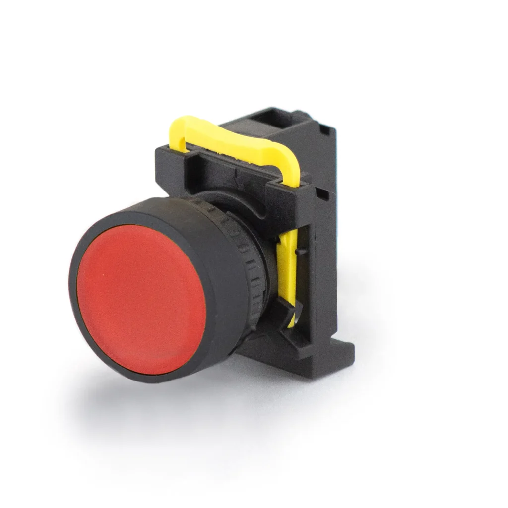
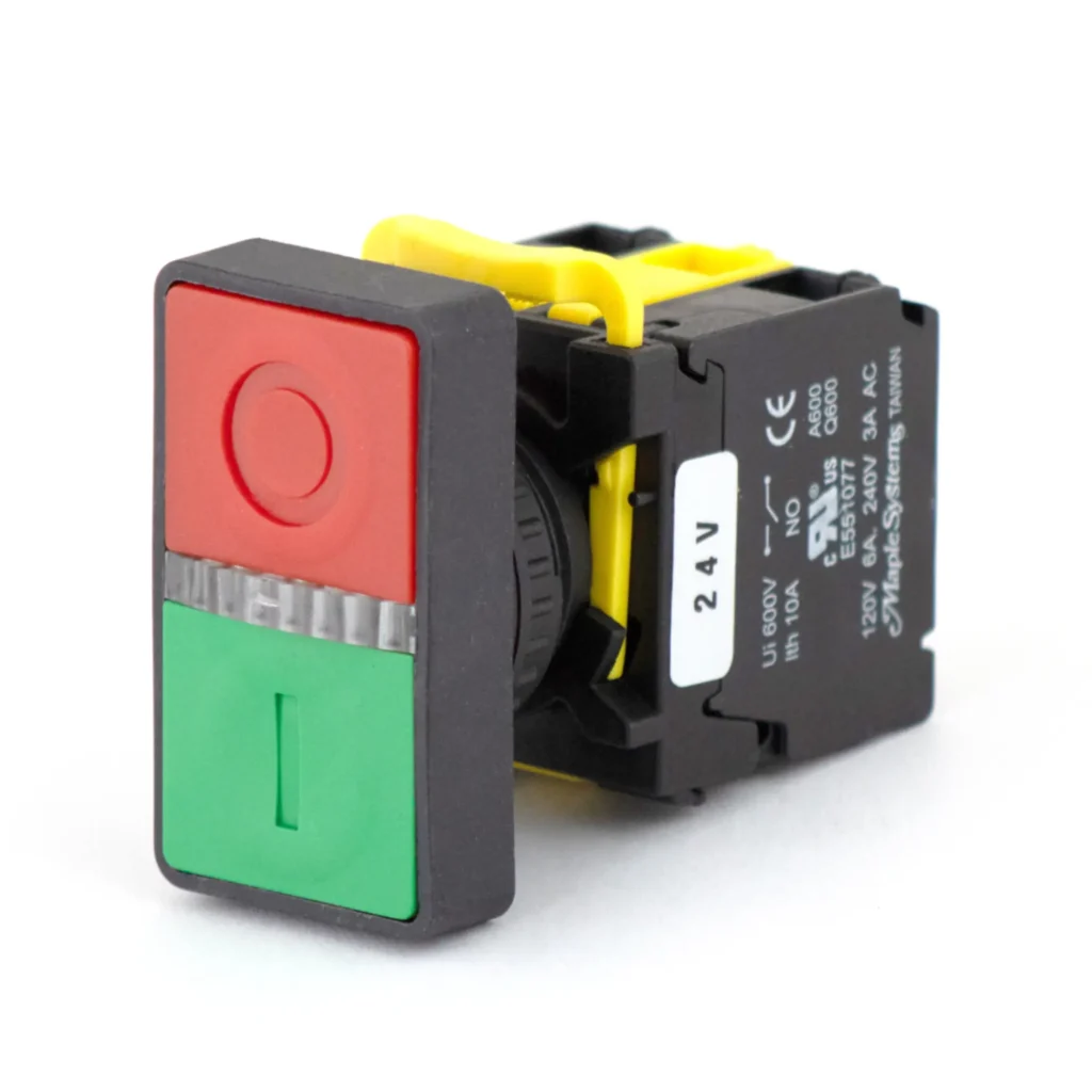
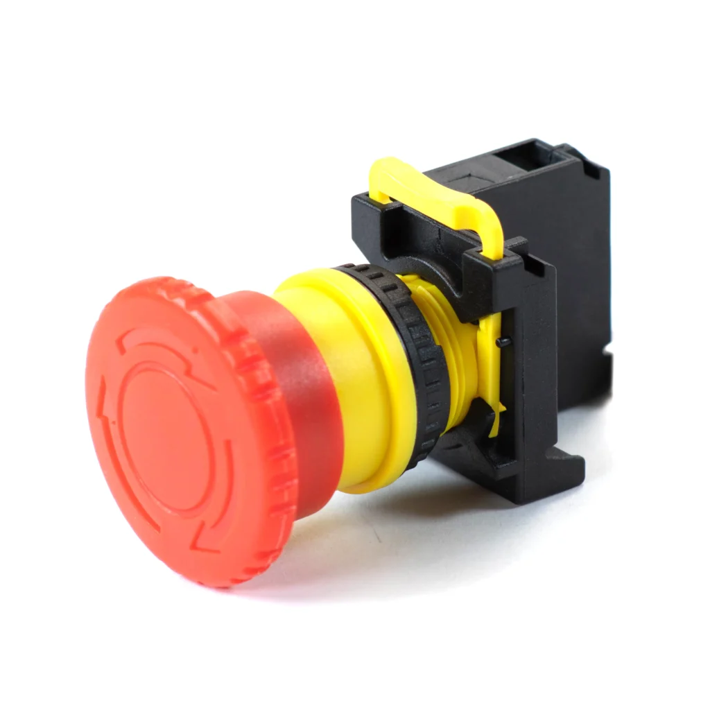
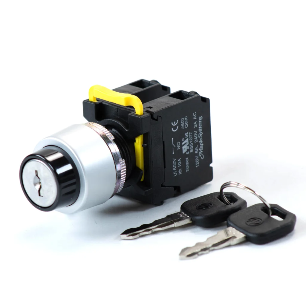
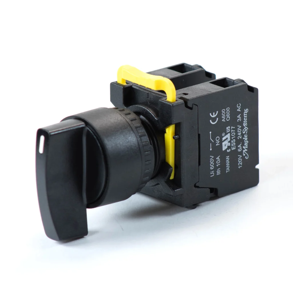
Every model fits a standard 22 mm panel cutout. Each device includes one normally closed safety contact. Optional contact blocks expand control functionality. The series carries CE and cURus certifications and an IP65 environmental rating. It also supports a 10 A thermal current. Both the actuator and contact block provide a one million operation mechanical life.
Indicator Lights for Machine Status Indication
Indicator lights provide immediate visual feedback about machine status. Operators can identify machine conditions without opening an HMI Panel or troubleshooting the control panel. These lights communicate normal operation, warnings, faults, and maintenance conditions. Standardized colors help operators recognize machine status quickly. Faster recognition reduces downtime and improves workplace safety.
The Maple Systems PBS110 Series is available with flat or full-lens designs. Models come in red, green, yellow, blue, and white. Following recognized color conventions from IEC 60204-1 and NFPA 79 helps create a consistent operator experience across machines and facilities.
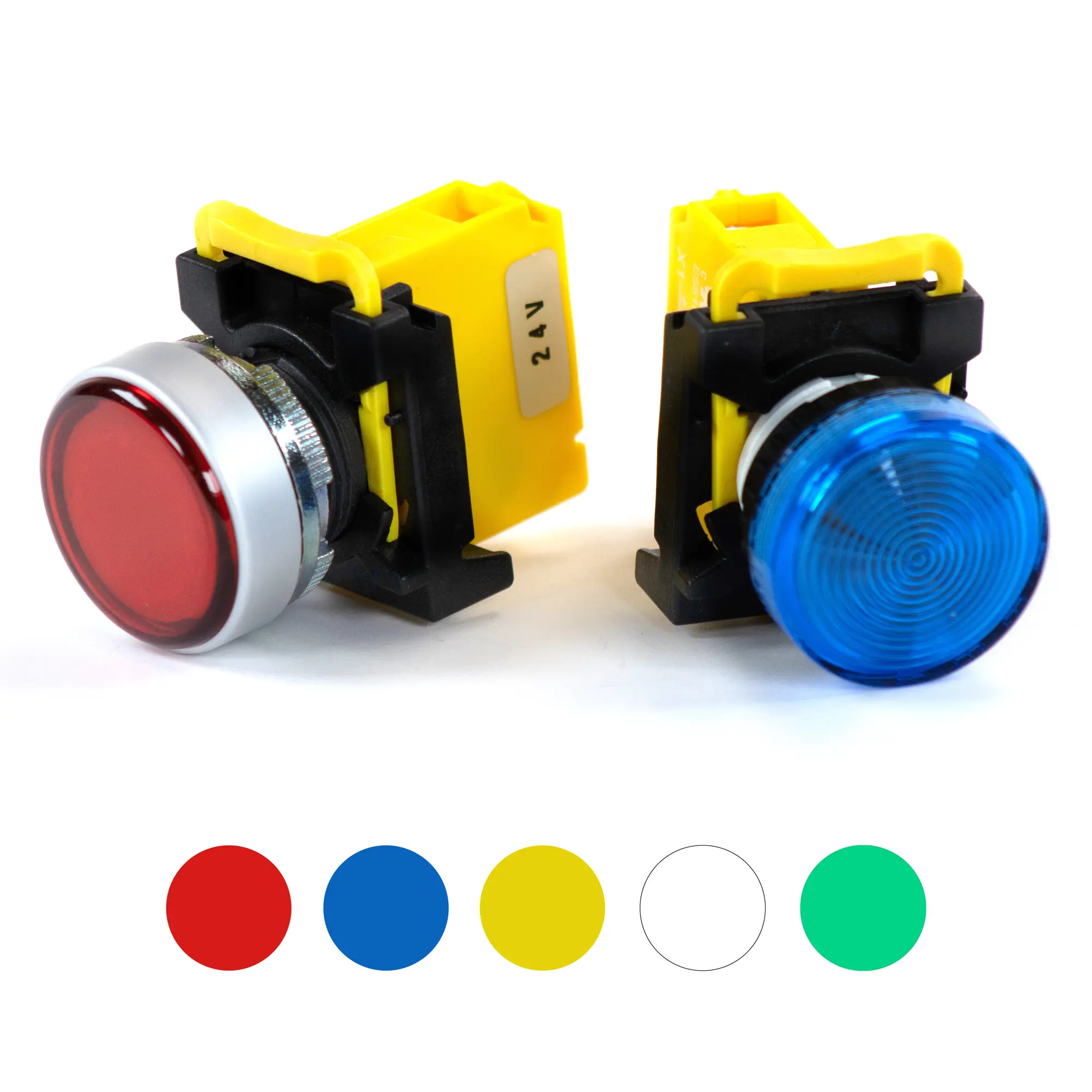
| Color | Industry Convention | Typical Applications |
|---|---|---|
| Red | Abnormal condition or fault | Emergency Stop, safety circuit open, machine fault, motor overload, critical alarm |
| Amber (Yellow) | Warning | Low material level, elevated temperature, low air pressure, approaching maintenance |
| Green | Normal operation | Machine running, automatic cycle active, conveyor operating |
| Blue | Mandatory operator action | Maintenance request, operator acknowledgment, manual intervention required |
| White | Neutral condition or power available | Control power on, machine ready, standby mode, initialization complete |
Each model features a bright 24 VDC LED and fits a standard 22 mm panel cutout. Every indicator includes a lamp holder and carries an IP65 rating. The series also meets CE and cURus certification requirements. Plastic and metal bezel options allow builders to match application requirements.
Machine Status Indication for Conveyor and Bottling Systems
Consider a packaging conveyor on a manufacturing line. A green indicator light shows normal conveyor operation. A yellow light warns operators when downstream equipment becomes blocked or product begins accumulating. A red light signals a machine fault caused by an emergency stop or motor overload. During maintenance, a blue light can indicate service mode. A white light can confirm that control power is available and the panel is energized.
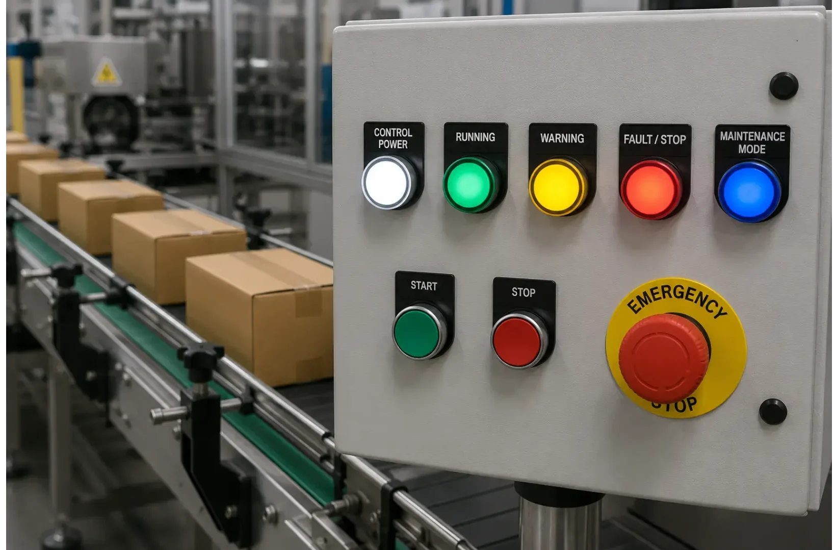
Operators and maintenance personnel can identify machine conditions from across the production floor. This visual feedback reduces troubleshooting time and helps restore production faster.
Another example would be on a bottling line, a green light indicates normal filling operations, an amber light warns of downstream congestion at the capper, and a red light identifies a fault that has halted the line.
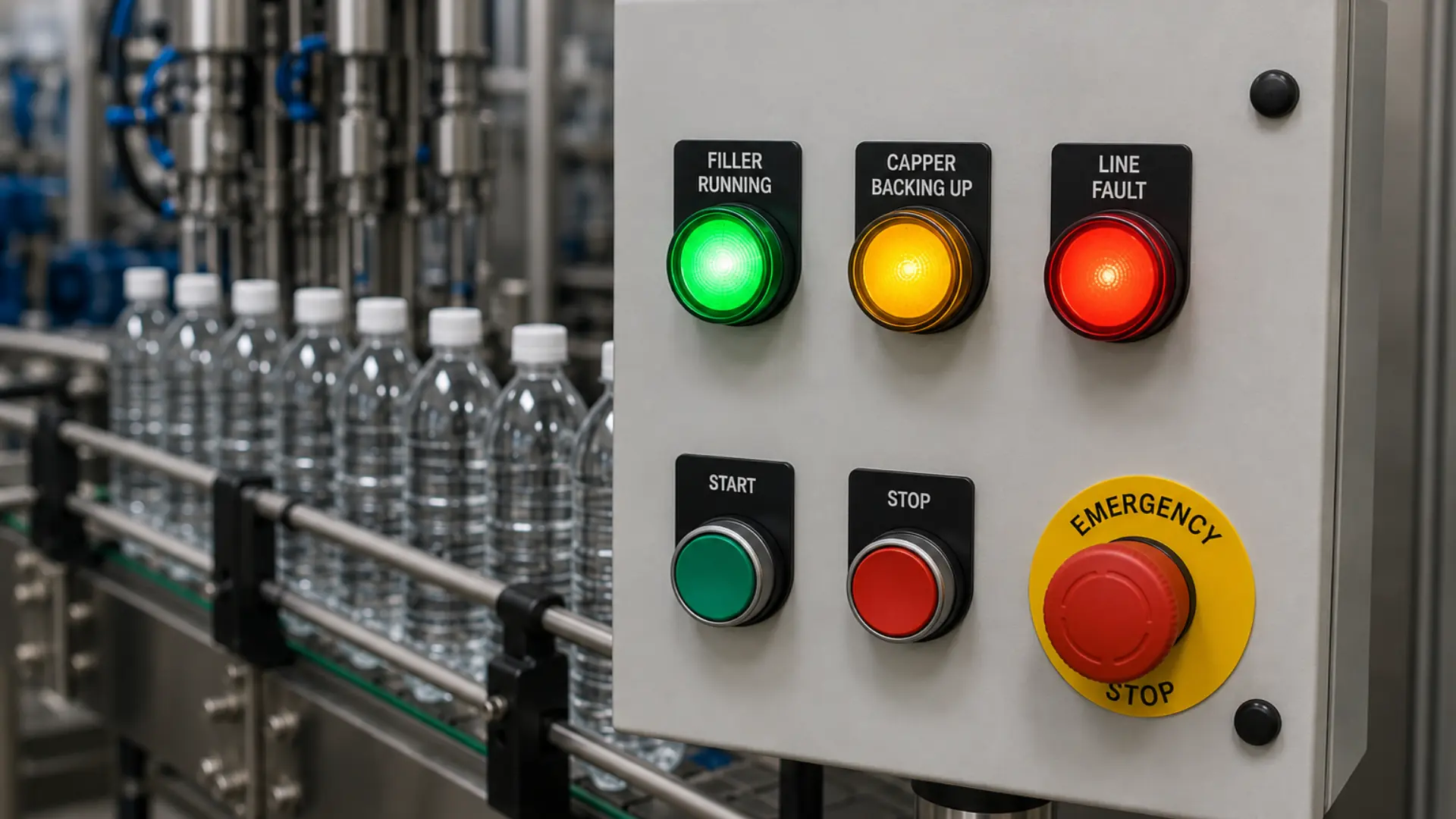
Operators can immediately determine the machine’s condition from a distance, reducing response time and unnecessary interaction with the HMI.
Momentary Push Buttons for Temporary Operator Input
Momentary push buttons provide temporary control inputs for industrial automation systems. Unlike maintained switches, they return to their normal position when released. This action makes them ideal for Start, Stop, Reset, Cycle Start, Jog, and Acknowledge functions. When connected to a PLC or relay-based control system, the push button sends a discrete input that triggers a programmed action. This design prevents unintended continuous operation.
The Maple Systems PBS111 Series is designed for industrial control panels and operator stations.
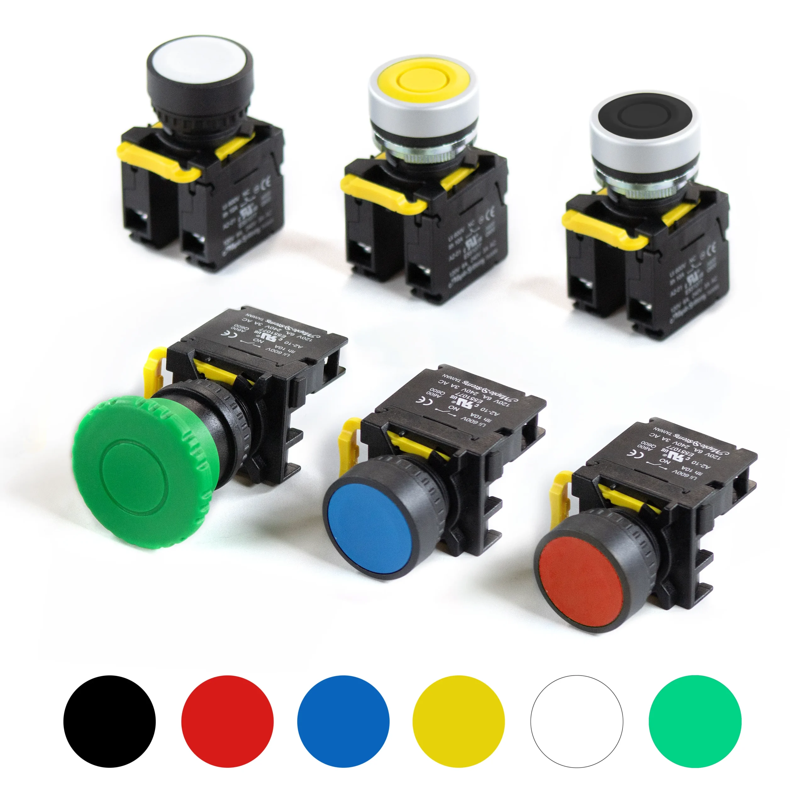
The series includes flat head, illuminated flat head, guard ring, and mushroom head styles. Multiple color options support standard machine control conventions. Every push button fits a standard 22 mm panel cutout. Each model carries an IP65 environmental rating and CE and cURus certifications. The actuator and contact block are rated for one million mechanical operations.
Multiple color options follow standard machine-control conventions, green or white for Start/On, red for Stop/Off, and blue for Reset, so operators can identify a button’s purpose at a glance. Contact blocks are available in normally open or normally closed configurations, selected to match the button’s function rather than its color: Start and other energize-on-press functions use a normally open contact, while Stop and other fail-safe functions use a normally closed contact that de-energizes the circuit when pressed. Optional contact blocks expand control functionality. Illuminated models feature a 24 VDC LED and include a lamp holder for improved visibility.
Manual Cycle Start on a Robotic Palletizer
Consider a robotic palletizing cell at the end of a packaging line. Before production begins, an operator loads an empty pallet and verifies that all safety gates are closed. The operator then presses a green Cycle Start push button. The PLC verifies all safety interlocks and machine conditions before starting the robot. If a fault interrupts production, the operator presses a dedicated Reset push button. The PLC clears the alarms and prepares the system for the next production cycle.
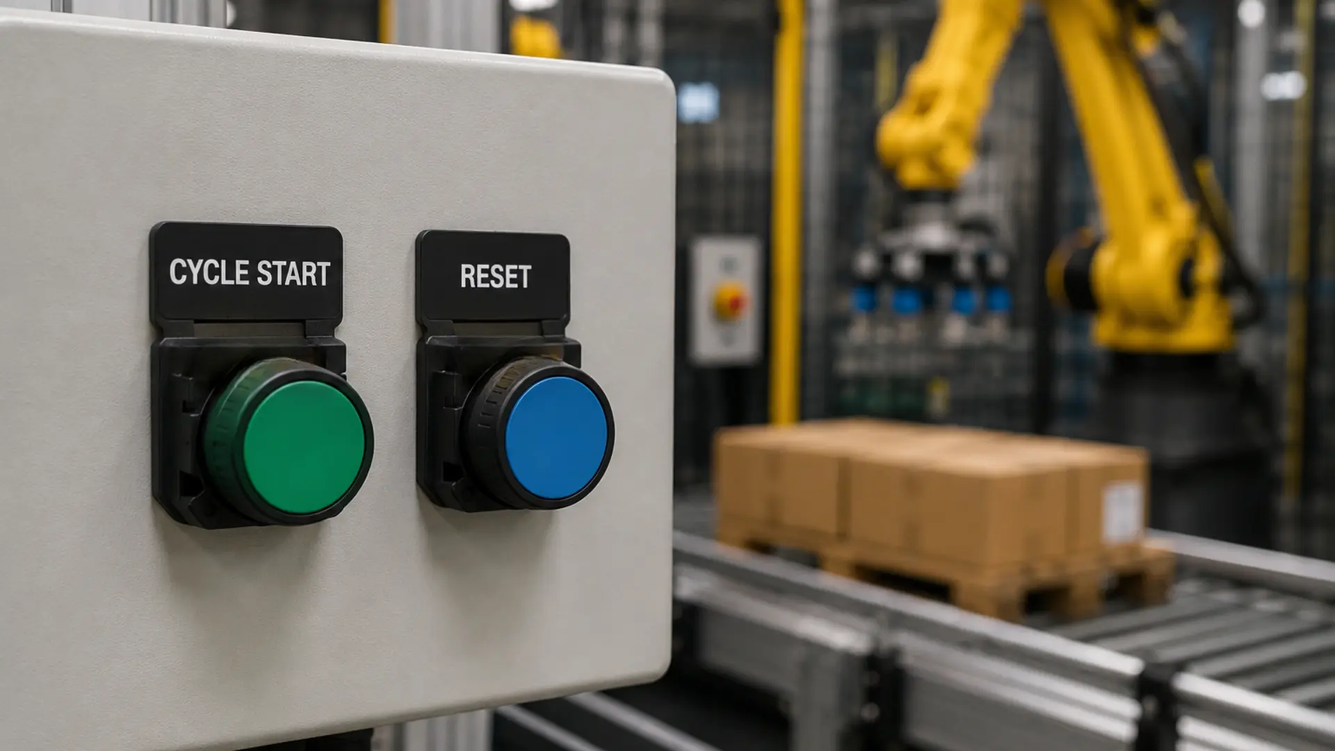
Momentary push buttons generate a temporary input instead of a continuous signal. This approach gives the PLC full control over machine operation and sequencing. It also improves operator safety and helps prevent unintended machine operation.
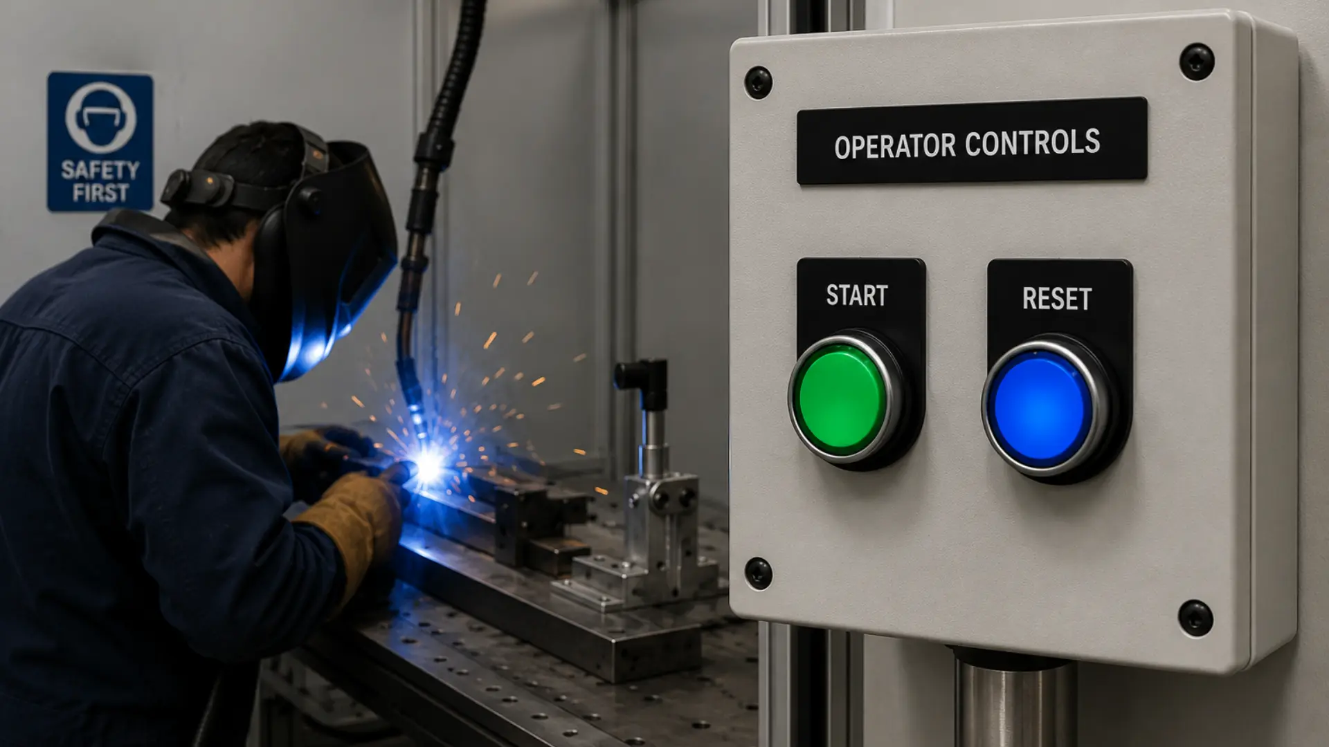
Another example would be at a manual welding station, the operator presses a green Start pushbutton to begin the welding cycle and a blue Reset pushbutton to clear a fault after the issue has been resolved. Each momentary button press changes the state of a discrete PLC input, allowing the control system to execute the next step in the machine sequence.
Latching Push Buttons for Maintained Operator Inputs
Latching pushbuttons (toggle push buttons) provide a maintained control input for industrial automation systems. Unlike momentary push buttons that return to their normal position after being released, toggle push buttons remain in their selected state until actuated again. This makes them well suited for applications where equipment or machine functions need to remain enabled or disabled without requiring the operator to continuously hold the button. Common applications include enabling auxiliary equipment, controlling conveyor zones, activating lighting circuits, or toggling machine functions that remain active until intentionally changed.
The Maple Systems PBS112 Series toggle push buttons are designed for industrial control panels and operator stations requiring reliable maintained control. The series includes standard flat head toggle push buttons, illuminated models with integrated 24 VDC LEDs, and double-touch configurations with flat or raised buttons for intuitive ON/OFF operation.
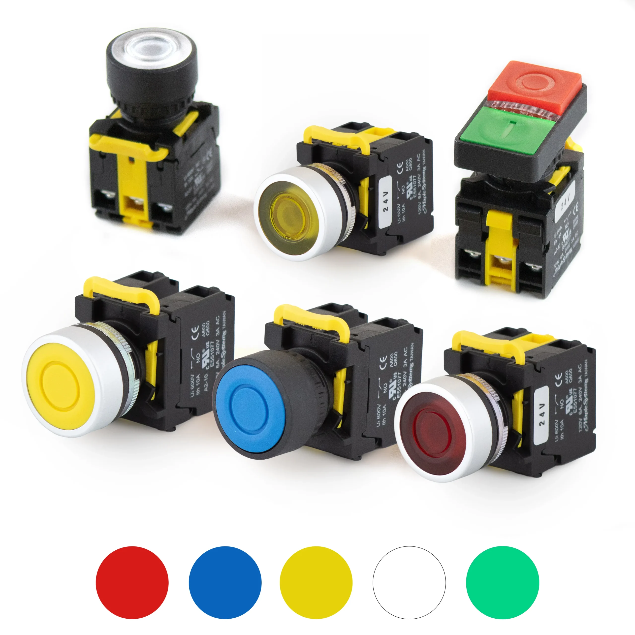
All models mount in a standard 22 mm panel cutout, feature an IP65 environmental rating for protection against dust and water, are CE and cURus certified, and utilize one normally open and one normally closed contact rated for one million mechanical operations. Additional contact blocks are also available, allowing engineers to expand control functionality when required.
Machine Enable and Equipment Control Applications
Consider a warehouse distribution center with multiple conveyor zones used for sorting packages. During routine operation, maintenance personnel may need to temporarily disable a single conveyor zone while leaving the remainder of the system operational. A maintained toggle push button installed on the local control station allows the operator to enable or disable that conveyor section with a single press. The PLC continuously monitors the maintained input and either permits or inhibits conveyor operation until the button is pressed again to change its state.
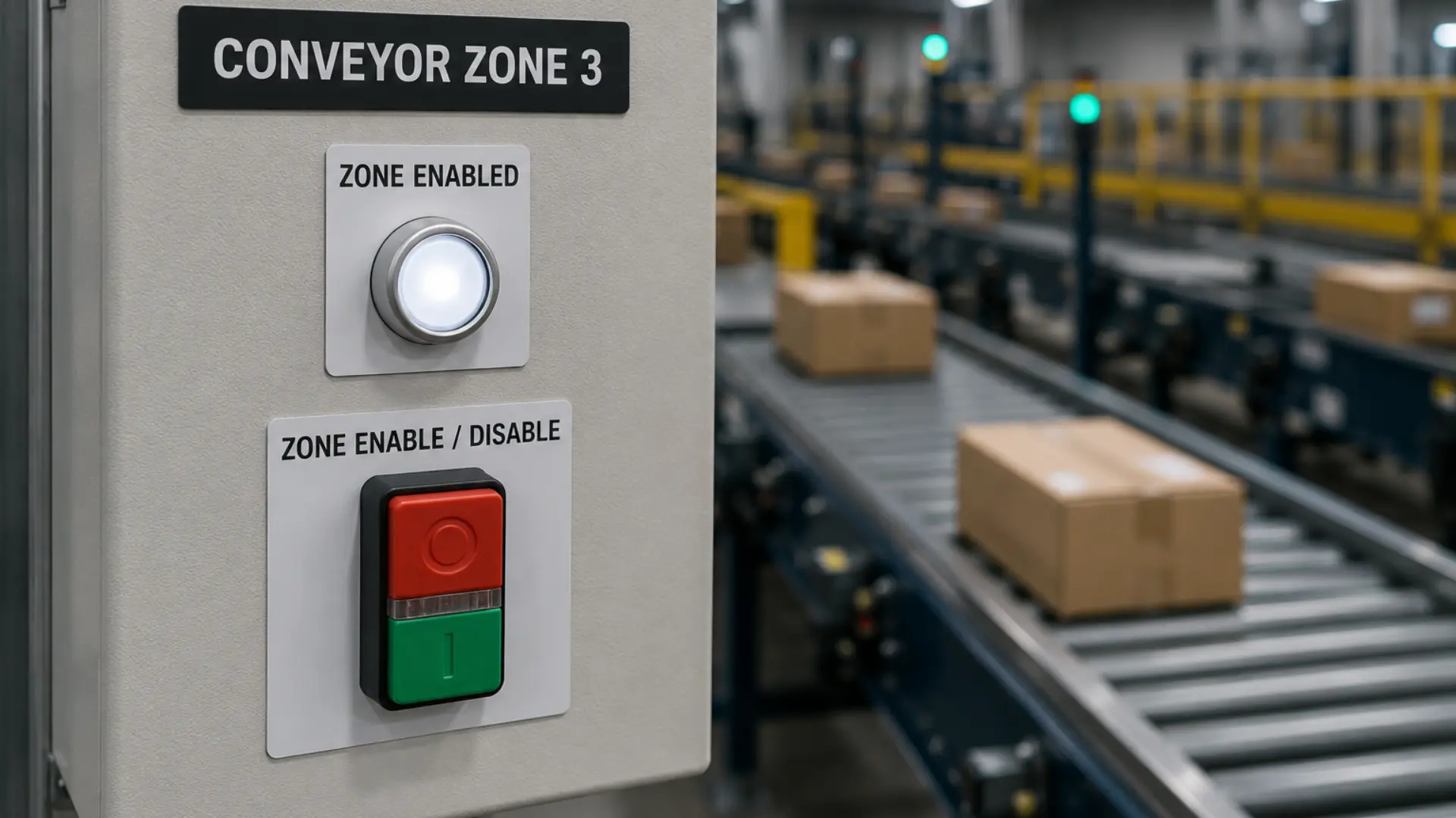
Because the button maintains its position, operators receive a clear indication of whether the conveyor zone is enabled or disabled without needing to hold the actuator. This provides a simple, reliable interface for controlling machine functions that remain active over extended periods while allowing the PLC to safely coordinate interlocks, alarms, and downstream equipment before restarting the conveyor.
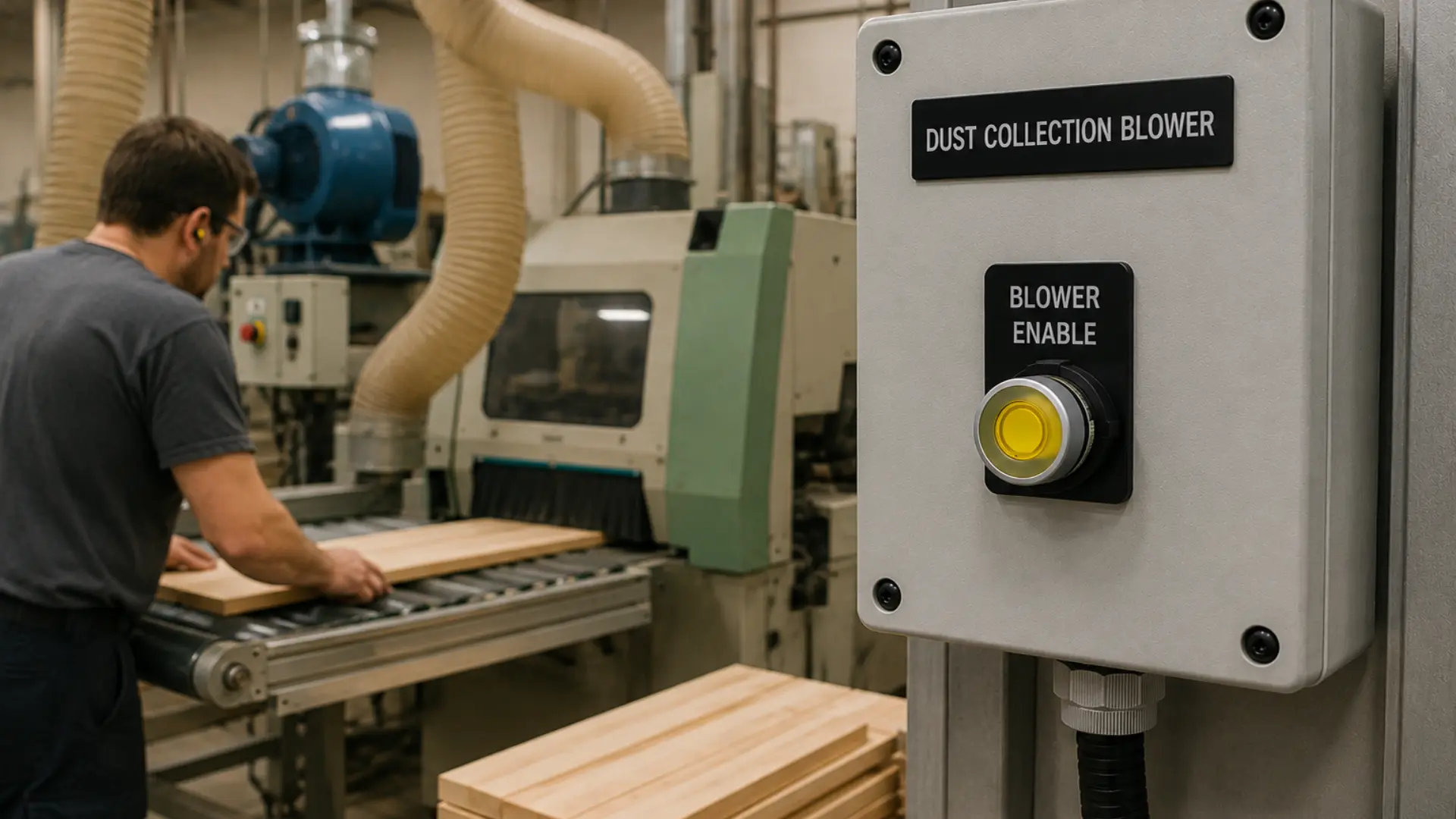
Another example would be on a woodworking production line, a maintained toggle switch enables or disables a dust collection blower for a specific machine or work cell. Because the switch remains in its selected position, the operator can leave the blower running without continuously holding the control.
2-Position Selector Switches for Simple Mode Selection
Two-position selector switches provide operators with two maintained operating states that remain selected until the switch is rotated again. They are commonly used anywhere equipment needs a clear choice between two operating conditions, such as Local/Remote, Auto/Manual, Enable/Disable, or Run/Service. Unlike push buttons, which initiate a temporary or maintained command, selector switches communicate the current operating mode through the physical position of the actuator, making machine operation easier to understand at a glance.
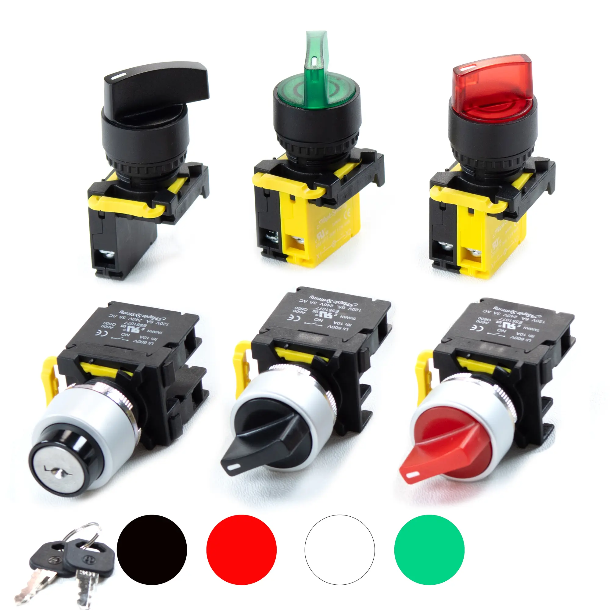
The Maple Systems PBS114 Series includes a wide range of 2-position selector switches designed for industrial control panels. Depending on the application, the series is available with short or long knob actuators, spring return or maintained operation, illuminated models with integrated 24 V LED lamp holders, and keyed versions that are available in drawable and non-drawable configurations for controlled access. All models mount in a standard 22 mm panel cutout, carry an IP65 environmental rating, are CE and cURus certified, feature a 600,000-operation actuator life, a one million operation contact block life, and allow additional contact blocks to be added for expanded control functions.
Non-Drawable Keyed Selector Switch: Local / Remote Control
In a wastewater lift station, a non-drawable keyed 2-position selector switch is used to select Local or Remote pump control. During normal operation, the switch remains in the Remote position, allowing the SCADA system to control pump operation. When maintenance personnel need to perform testing or troubleshooting, they use the key to switch the selector to Local, transferring control to the pump control panel.
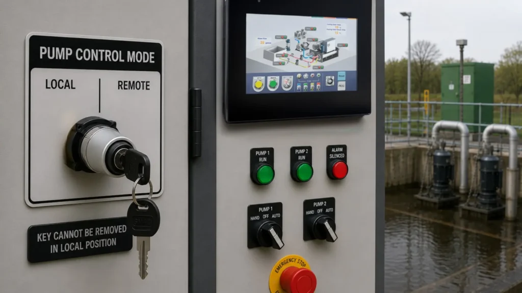
Because the key cannot be removed while the selector is in the Local position, maintenance personnel have a clear visual reminder that the system is no longer operating under remote control. The maintained selector position also allows anyone approaching the panel to immediately identify the active operating mode without opening the HMI. While the keyed selector helps prevent unauthorized mode changes, it should not be used as a substitute for proper lockout/tagout (LOTO) procedures.
Drawable Keyed Selector Switch: Auto / Manual Machine Setup
On an automated packaging machine, a drawable keyed 2-position selector switch selects between Automatic and Manual Setup modes. During production, the machine operates in Automatic, where the PLC controls the complete packaging sequence. Authorized technicians can insert the key and switch the machine to Manual Setup to jog conveyors, verify sensors, and perform changeovers.
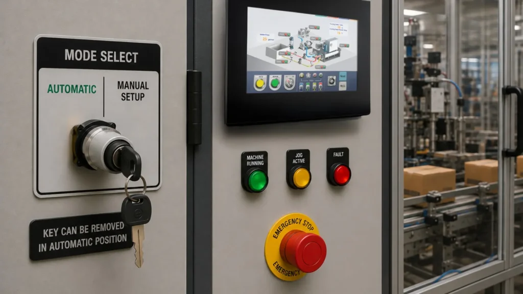
Once the selector is returned to the Automatic position, the key can be removed and stored by maintenance personnel, preventing unauthorized operators from entering setup mode. The physical position of the selector provides immediate visual confirmation of the active operating mode, while the maintained mechanism keeps the selected mode active until it is intentionally changed.
3-Position Selector Switches for Multiple Operating Modes
Three-position selector switches allow operators to select between three distinct machine states using a single control device. They are commonly used when equipment requires an intermediate operating mode in addition to two primary states, reducing the number of separate switches required on the control panel. Depending on the application, the center position may represent a neutral or off state, while spring-return models automatically return to the center position after momentary operation.
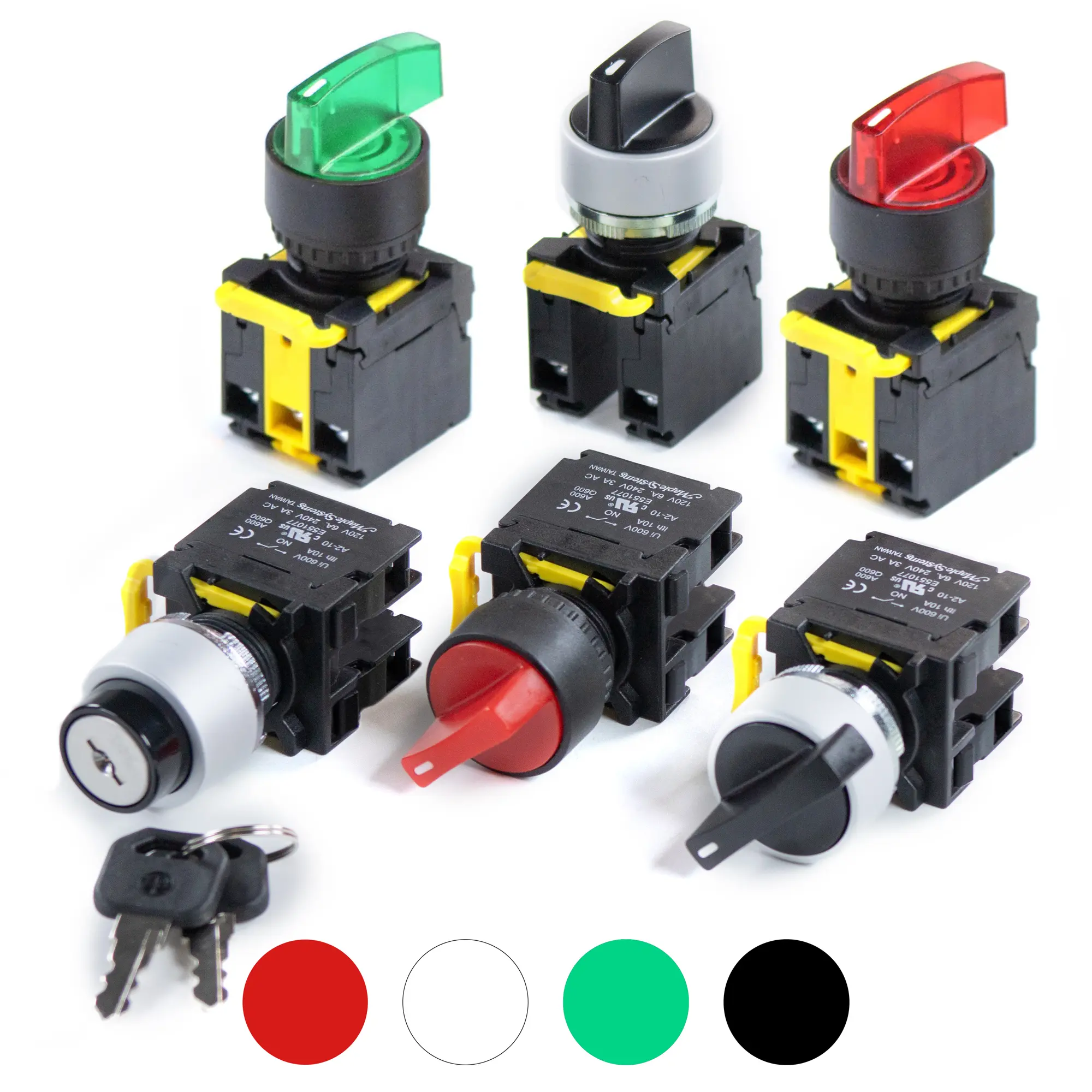
The Maple Systems PBS115 Series offers a wide range of 3-position selector switches, including maintained, spring-return, illuminated, long-knob, short-knob, and keyed drawable models. All versions mount in a standard 22 mm panel opening and feature an IP65 rating, CE and cURus certifications, two normally open contacts, a 600,000-operation actuator life, and one million operation contact blocks. Illuminated models include an integrated 24 V LED lamp holder, while optional contact blocks allow additional control circuits to be added as application requirements grow.
Hand-Off-Auto and Machine Mode Selection Applications
A Hand-Off-Auto (HOA) selector switch is commonly used in water and wastewater facilities, HVAC systems, and industrial pumping applications. The three-position selector allows operators to choose between Hand, Off, and Auto operation using a single control device.
A Hand-Off-Auto (HOA) selector on a motor starter allows an operator to run a fan manually for testing, switch it off for servicing, or return it to automatic PLC control, all from a single 3-position selector switch.
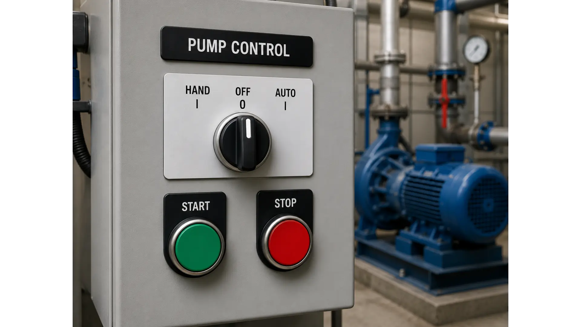
Using a single 3-position selector switch reduces panel space compared to multiple pushbuttons or switches while providing immediate visual confirmation of the active operating mode. The PBS115 Series also offers spring-return-to-center models for applications requiring momentary mode selection, as well as maintained models that remain in the selected position until intentionally changed. Each outer position operates its own normally open contact, allowing the PLC to independently detect whether Hand or Auto has been selected. For applications requiring restricted access, keyed drawable models help limit who can change operating modes, although they should not be considered a substitute for proper lockout/tagout (LOTO) procedures.
Another example is for an overhead bridge crane that can operate in three different modes: Maintenance, Off, and Automatic Production. A 3-position selector switch mounted on the control panel allows maintenance personnel to select the desired operating mode before the PLC enables crane functions.
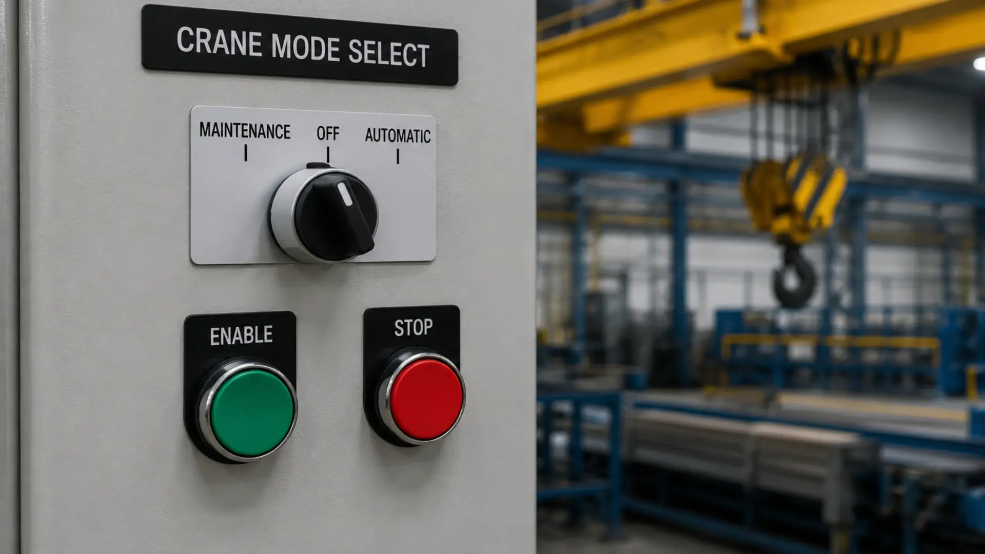
In the Maintenance position, the PLC permits limited manual movement for servicing and inspections. The center Off position disables crane motion, while the Automatic position returns the crane to normal production control through the plant automation system. Using a single 3-position selector switch simplifies operator interaction while providing a clear indication of the crane’s current operating mode.
Latching Emergency Stop Push Buttons for Personnel and Equipment Safety
A latching emergency stop (E-Stop) is one of the most important safety devices in industrial equipment. Unlike standard push buttons, an E-Stop immediately stops machine operation during an emergency. It remains mechanically latched until an operator intentionally resets it. This design prevents unexpected restarts after a hazardous condition. As a result, it protects both personnel and equipment.
The Maple Systems PBS113 Series supports emergency stop applications. The series includes 35 mm and 40 mm red mushroom head actuators. It also offers illuminated models with integrated 24 V LED lamp holders and keyed versions for controlled reset.
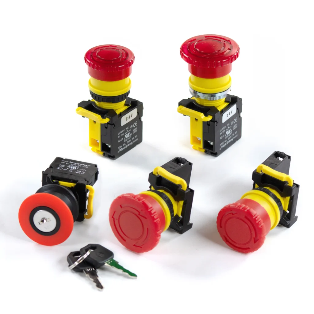
Every PBS113 Series Emergency Stop mounts in a standard 22 mm panel cutout. Each device uses one normally closed safety contact with positive-opening (direct-opening-action) operation in accordance with IEC 60947-5-5. When an operator presses the E-Stop, the mechanism physically forces the contact open, even in the unlikely event the contact has welded, ensuring the stop function does not rely solely on spring force. The normally closed contact also provides inherent fail-safe operation because a broken wire or loose terminal opens the circuit and commands a stop. Additional contact blocks can be added to expand control functionality. The PBS113 Series carries CE and cURus certifications, an IP65 environmental rating, and supports a 10 A thermal current. Both the actuator and contact block are rated for one million mechanical operations.
Per ISO 13850, the Emergency Stop uses a red mushroom-head actuator on a yellow background for immediate identification. Resetting the latched Emergency Stop only restores the safety circuit; it never restarts the machine. Operators must issue a separate, deliberate Start command before machine operation can resume. For proper machine safety, integrate the Emergency Stop into a monitored safety function, such as a safety relay or safety controller, designed to achieve the required Performance Level (PL) in accordance with ISO 13849-1 or the required Safety Integrity Level (SIL) in accordance with IEC 62061, rather than relying on the E-Stop as a standalone control circuit.
Emergency Stop Applications in Automated Palletizing Cells
An automated palletizing cell uses a robotic arm to stack finished products before shipment. Operators may enter the work area to clear fallen boxes or inspect equipment. If a hazardous condition occurs, the operator presses the nearby latching emergency stop.
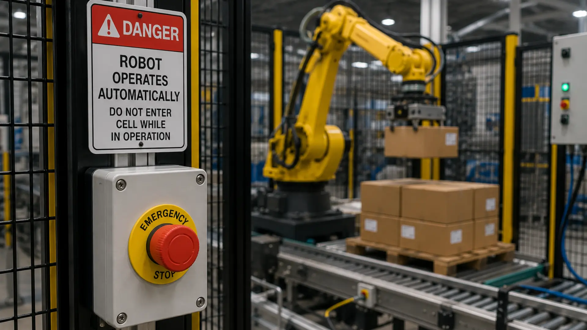
Pressing the E-Stop immediately removes the machine’s run command. The button remains mechanically latched until the operator clears the hazard and intentionally resets the device. This prevents the machine from unexpectedly restarting when power returns or an obstruction has been removed.
Some applications require only authorized personnel to reset the Emergency Stop after investigating a hazardous condition. In these cases, a keyed Emergency Stop restricts the reset function while still allowing anyone to press the button during an emergency. The key controls only the reset mechanism, it does not affect the Emergency Stop function itself.
In an automated palletizing cell, operators can press the latching Emergency Stop at any time to stop hazardous machine motion when an unsafe condition occurs. After activation, the keyed Emergency Stop remains mechanically latched until an authorized supervisor or maintenance technician verifies that the hazard has been resolved and resets the device with the key.
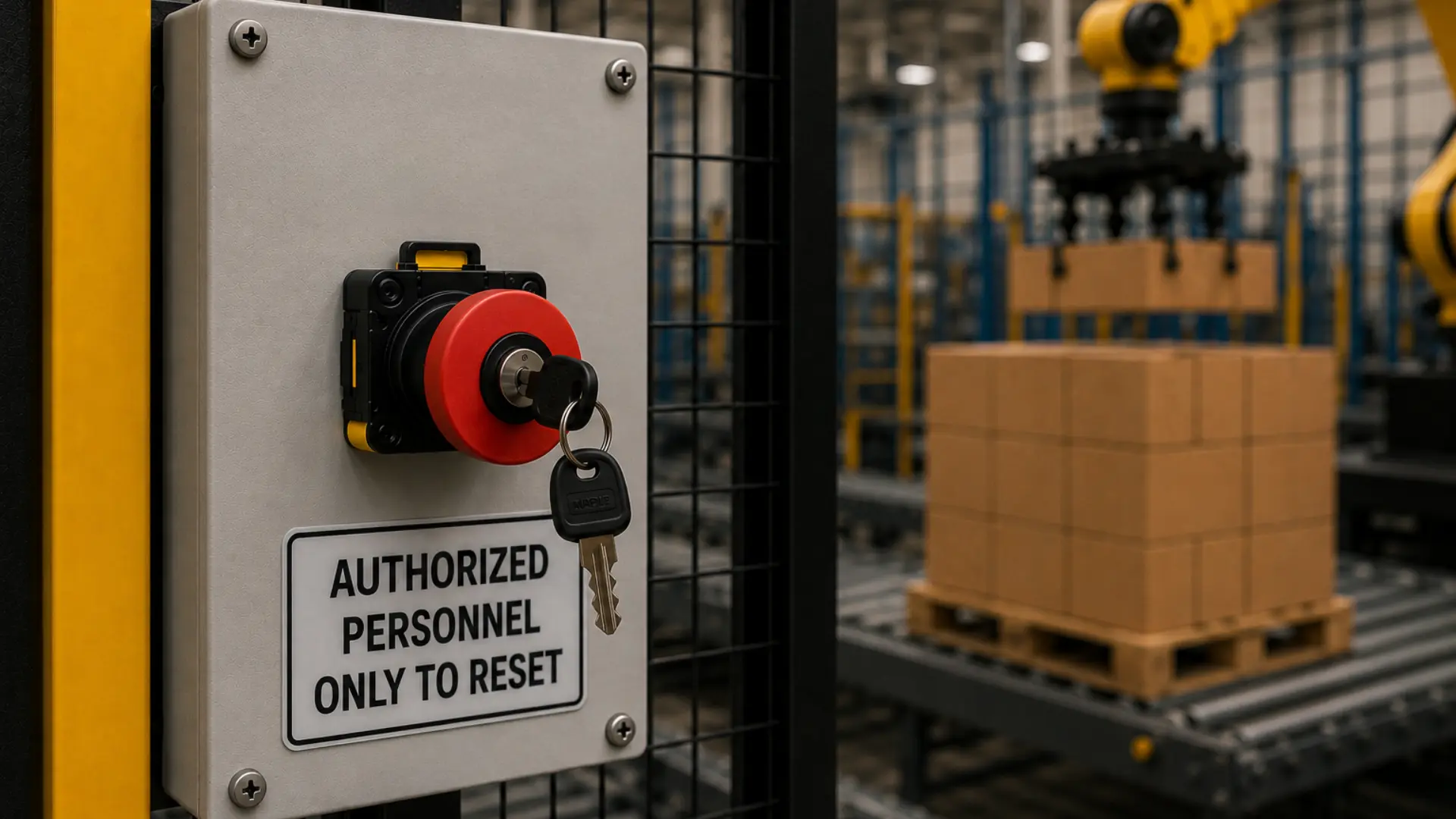
Only authorized personnel can reset the E-Stop with the appropriate key, helping prevent unauthorized or accidental machine restarts. After the reset, the PLC completes its startup sequence and verifies all safety conditions before allowing production to resume. This process improves operational safety while ensuring the Emergency Stop remains accessible to everyone during an emergency.
Final Takeaway
Industrial operator interface devices provide the discrete inputs and visual outputs that connect personnel to machine control systems. Whether interfacing with PLC Controllers, safety relays, or conventional control circuits, indicator lights, push buttons, selector switches, and latching emergency stops each perform a distinct function within the overall control architecture. Proper device selection, combined with appropriate electrical integration and control logic, improves system reliability, enhances operator interaction, and supports safe machine operation throughout the equipment lifecycle.
Next Steps
Whether you’re designing a new machine or upgrading an existing control system, selecting the appropriate operator interface devices is a critical part of your control panel design. Evaluate the required control functions, operating modes, environmental conditions, and safety requirements to determine the best combination of indicator lights, push buttons, selector switches, and emergency stop devices. With the right components in place, your next control panel can provide intuitive operator interaction, reliable performance, and long-term maintainability.
Resources & Documentation
The following documentation are specific to the hardware used in this tutorial and will help with setup, configuration, and programming:
- PBS110 Datasheet
- PBS111 Datasheet
- PBS112 Datasheet
- PBS113 Datasheet
- PBS114 Datasheet
- PBS115 Datasheet
Looking for additional learning resources? Explore our library of tutorials, example projects, and software tools to help you get the most out of your system:
Also, browse our Support Center for a complete list of installation guides, FAQs, and additional technical documentation.

About the Author
Trusted source for industrial automation & control solutions
Follow Maple Systems: