Introduction
All Maple Systems HMIs programmed with EBPro (EasyBuilder Pro), including every cMT X Series and cMT Series model, are compatible with Siemens S7-400 (Ethernet). Configure your Controller and HMI/cMT with the following parameters to establish reliable communication.
Supported Series: Siemens S7-400 Ethernet PLC
Website: http://www.siemens.com/entry/cc/en/
HMI Settings
| Parameters | Recommended | Options | Notes |
|---|---|---|---|
| PLC type | Siemens S7-400 (Ethernet) | ||
| PLC I/F | Ethernet | ||
| Port no. | 102 | ||
| Link type | PG | PC, OP | |
| Rack | 0 | 0–7 | |
| CPU slot | 3 | 1–31 | To connect with S7-1200, Slot 1 must be selected. |
| PLC sta. no. | 0 | 0–31 |
Device Address
| Bit/Word | Device Type | Format | Range | Memo |
|---|---|---|---|---|
| B | I | DDDDo | 0 ~ 40957 | Input (I) |
| B | Q | DDDDo | 0 ~ 40957 | Output (O) |
| B | M | DDDDo | 0 ~ 40957 | Bit Memory |
| B | DBnBit | FFFFFDDDDo | 0 ~ 6553599997 | |
| B | DBxBit | FFFFFDDDDD | 0 ~ 10700655357 | |
| B | DB1Bit–DB99Bit | DDDDDo | 0 ~ 655357 | Data Register Bit |
| W | IW | DDDD | 0 ~ 4095 | Input (I) |
| W | QW | DDDD | 0 ~ 4095 | Output (O) |
| Byte | MB | DDDD | 0 ~ 4095 | Bit Memory Byte |
| W | MW | DDDD | 0 ~ 4095 | Bit Memory |
| DW | MD | DDDD | 0 ~ 4094 | |
| Byte | DBBn | FFFFFDDDD | 0 ~ 655359999 | Data Register Byte |
| Byte | DBBx | FFFFFDDDDD | 0 ~ 1070065535 | |
| W | DBn | FFFFFDDDD | 0 ~ 655359999 | Data Register (must be even) |
| W | DBx | FFFFFDDDDD | 0 ~ 1070065535 | |
| DW | DBDn | FFFFFDDDD | 0 ~ 655359999 | Data Register Double Word (must be even) |
| DW | DBDx | FFFFFDDDDD | 0 ~ 1070065535 | |
| W | DBn_String | FFFFFDDDD | 0 ~ 655359999 | |
| W | DBx_String | FFFFFDDDDD | 0 ~ 1070065535 | |
| W | DBn_String1 | FFFFDDDD | 0 ~ 40969999 | |
| W | DBx_String1 | FFFFFDDDDD | 0 ~ 1070065535 | |
| DW | DBDn_String | FFFFFDDDD | 0 ~ 655359999 | |
| DW | DBDx_String | FFFFFDDDDD | 0 ~ 1070065535 | |
| W | DB1–DB99 | DDDDD | 0 ~ 65535 | Data Register (must be even) |
NOTE: Double word and floating point values must use the DBDn device type.
EBPro (EasyBuilder) Device Setting Steps
Open EBPro (EasyBuilder) and Create a New Project
Open EasyBuilder, go to File u0026gt; New, select your HMI model, and press OK.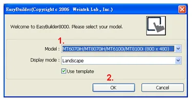
Open System Parameter Settings and Add a New Device
The System Parameter Settings window opens. Click New.Select the PLC Type
In the Device Properties dialog, set the PLC type to SIEMENS S7-400 (Ethernet).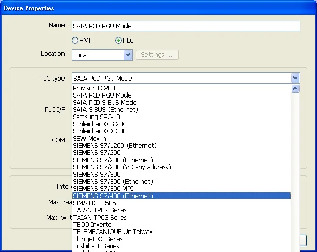
Open the IP Address Settings Dialog
Press Settings to configure the connection parameters.Configure S7-400 Connection Parameters
Set the S7-400 IP address, Port no., Link type, Rack, and CPU slot. These values must match the PLC settings.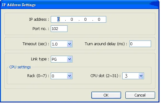
Confirm the Completed Device Configuration
The device configuration is complete. The Device Properties dialog now shows the configured SIEMENS S7-400 (Ethernet) connection.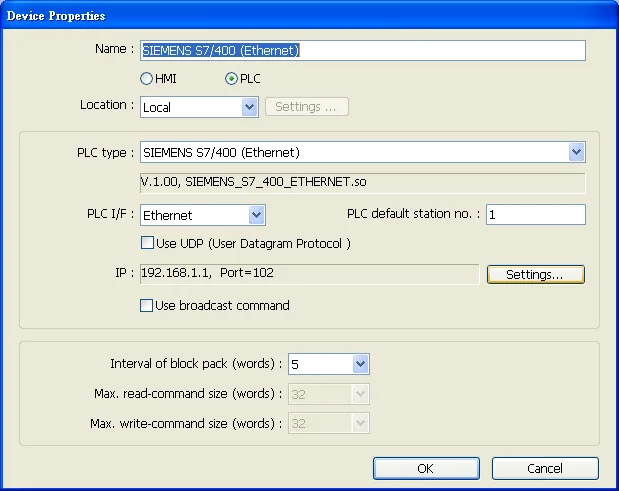
How to Import Tag
SIEMENS STEP 7 allows building files of user-defined tags (*.dif and *.AWL) and importing them in EBPro (EasyBuilder Pro) via System Parameter Settings. The following describes how to build and import these two file types.
Building a *.dif File
Create User-Defined Tags in Symbols
In SIMATIC Manager, navigate to your program’s Symbols and create user-defined tags in the Symbol Editor.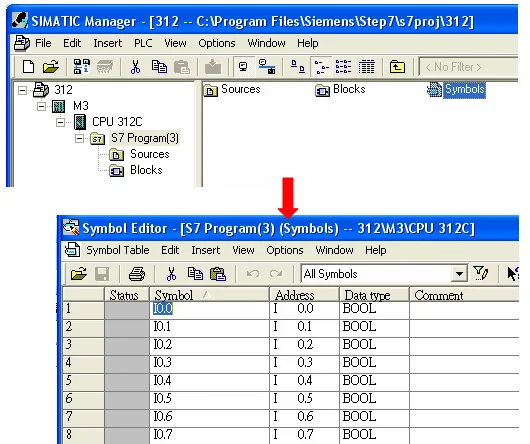
Export the Symbol Table as a DIF File
In the Symbol Editor, go to Symbol Table u0026gt; Export. In the Export dialog, specify a file name (e.g.,PLC_Tag.dif), set the file type to *Data Interchange Format (.DIF), and click Save**.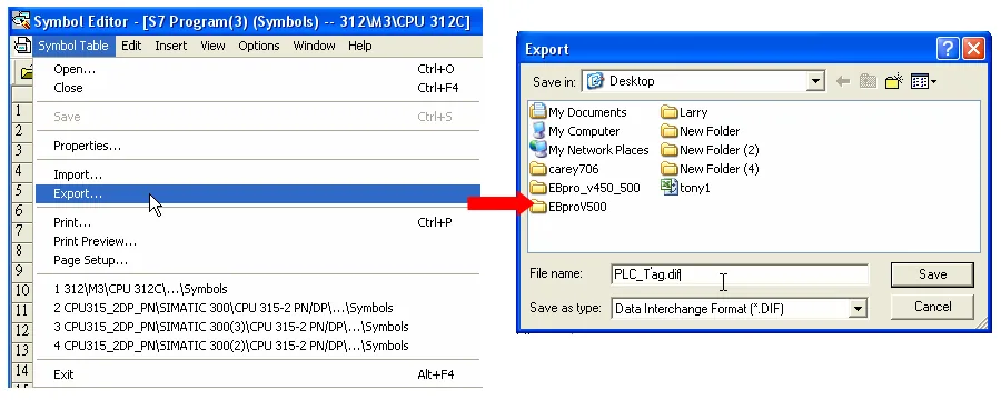
Building a *.AWL File
Create Data Blocks in the Blocks Folder
In SIMATIC Manager, open your program’s Blocks folder and create the required data blocks (DB1, DB2, etc.).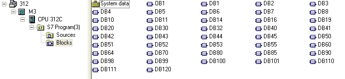
Open LAD/STL/FBD and Generate Source
From the Windows Start menu, navigate to STEP 7 u0026gt; LAD, STL, FBD – Programming S7 Blocks. In the program block editor, go to File u0026gt; Generate Source.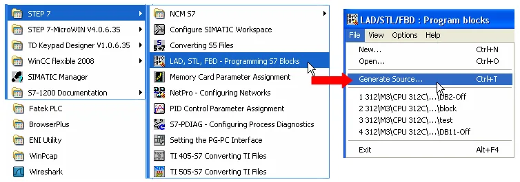
Specify Sources as the Storage Path and Enter the File Name
In the New dialog, select Sources as the storage path, enter a file name (e.g.,Object_Tag), then click OK.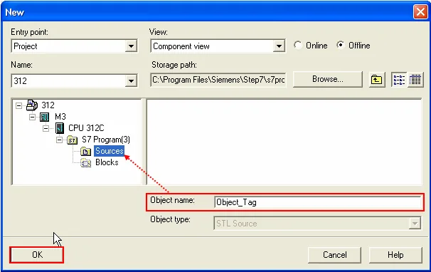
Select the Blocks to Export
In the Generate source Object_Tag dialog, move the desired data blocks from Blocks Not Selected to Blocks Selected, then click OK.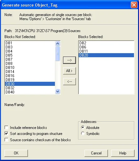
Export the Source File as an AWL File
Back in SIMATIC Manager, under Sources, right-click the saved source object and choose Export Source. In the Export source dialog, save the file as an*.AWLfile.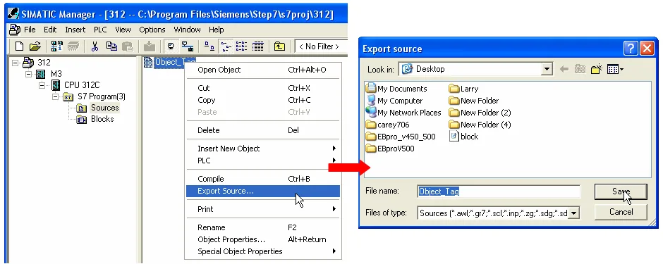
Importing Tags into EBPro (EasyBuilder)
Click Import Tag in System Parameter Settings
The generated.difand.AWLfiles can be imported in EBPro (EasyBuilder Pro) via System Parameter Settings by clicking Import Tag. In the Import Address Tag dialog, browse to select both the DIF file and the AWL file, then click OK.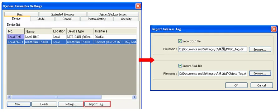
Confirm Successful Import
A confirmation dialog appears indicating that tag information was imported successfully.
Wiring Diagram
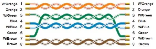
The diagram below shows the Ethernet cable wiring.