
Introduction
All Maple Systems HMIs programmed with EBPro (EasyBuilder Pro), including every cMT X Series and cMT Series model, are compatible with Yokogawa FA-M3. Configure your Controller and HMI/cMT with the following parameters to establish reliable communication.
Supported Series: FA-M3 CPU SP35-5N, SP55-5N CPU port, F3LC11 Computer Link module
HMI Settings
| Parameters | Recommended | Options | Notes |
|---|---|---|---|
| PLC type | YOKOGAWA FA-M3 | ||
| PLC I/F | RS232 | ||
| Baud rate | 19200 | 9600 ~ 115200 | |
| Data bits | 8 | 7, 8 | |
| Parity | Even | Even, Odd, None | |
| Stop bits | 1 | 1, 2 | |
| PLC sta. no. | 1 | 1-32 | |
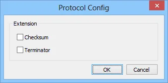
| cMT-G03 Gateway | Yes | The [Protocol Config] settings of cMT-G03 and upper HMI must be the same. |
PLC Settings
| Communication mode | Setting |
|---|---|
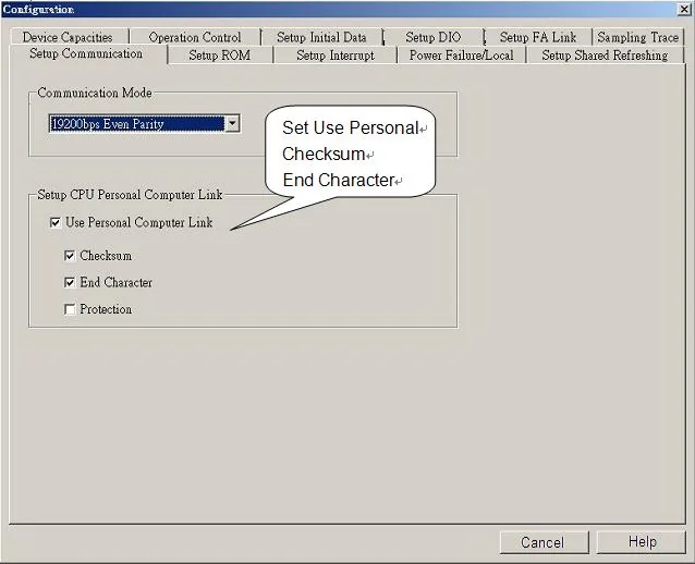
| Communication mode | Use Personal Communication Link |
| Use checksum | Enabled |
| Use End Character | Enabled |
WideField Communication Setting
For WideField communication setting, select [Tool] / [Set Environment]. The default connection method is Automatic Recognition — WideField software will connect to the current PLC and retrieve its communication settings automatically. If the PLC communication configuration is already known, select Fixed mode to connect more quickly.
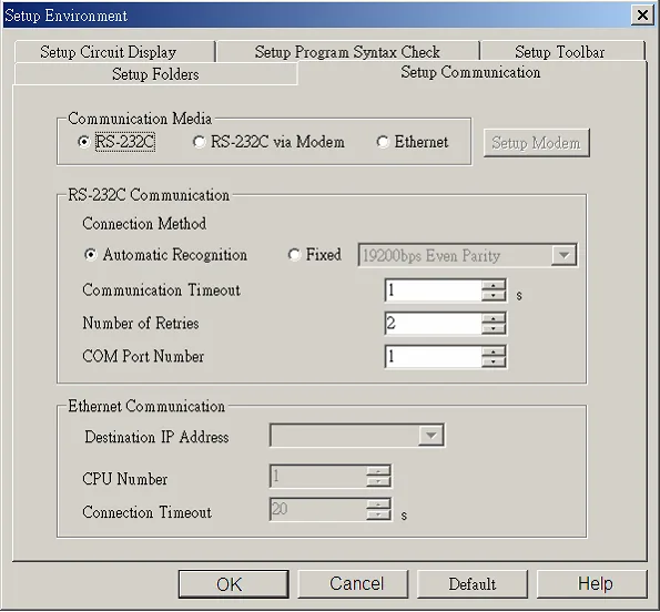
NOTE: Since Personal Computer Link is used, connecting to the PLC will delay approximately 20 seconds for communication testing.
Yokogawa PLC Communication Setting
FA-M3 CPU SP55-5N (same as SP35-5N)
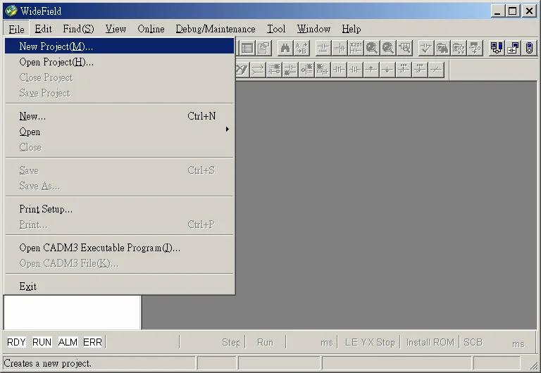
Use [File] / [New Project] to create a new project.
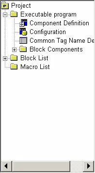
In the project tree, open Configuration to set up communication.
Device Address
| Bit/Word | Device | Format | Range | Memo |
|---|---|---|---|---|
| B | X | DDDDD | 0 ~ 71664 | |
| B | Y | DDDDD | 0 ~ 71664 | |
| B | I | DDDDD | 1 ~ 65535 | |
| B | M | DDDD | 1 ~ 9984 | |
| B | L | DDDDD | 0 ~ 78192 | |
| B | TU | DDD | 0 ~ 512 | |
| B | CU | DDD | 0 ~ 512 | |
| W | D | DDDDD | 1 ~ 65535 | |
| W | B | DDDDDD | 1 ~ 262144 | |
| W | V | DDD | 1 ~ 256 | |
| W | W | DDDDD | 1 ~ 78192 | |
| W | Z | DDDD | 1 ~ 1024 | |
| W | F | DDDDDD | 1 ~ 524288 | |
| W | TP | DDD | 1 ~ 512 |
Wiring Diagram
NOTE: The serial port pin assignments may vary between HMI models.
RS-232
| HMI | Direction | PLC |
|---|---|---|
| Pin assignments | RS232 9P D-Sub Male | |
| Rx | ↔ (bidirectional) | 3 TX |
| Tx | ↔ (bidirectional) | 2 RX |
| GND | ↔ (bidirectional) | 5 GND |
| ↕︎ (tie) | 7 8 |