Introduction
All Maple Systems HMIs programmed with EBPro (EasyBuilder Pro), including every cMT X Series and cMT Series model, are compatible with CANbus 2.0A/2.0B General and SAE J1939 Symbolic. Configure your Controller and HMI/cMT with the following parameters to establish reliable communication.
Supported series: CAN Bus 2.0A / CAN Bus 2.0B / SAE J1939
HMI Settings
| Parameters | Recommended | Options | Notes |
|---|---|---|---|
| PLC type | CAN Bus 2.0A/2.0B General and SAE J1939 | ||
| Baud rate | 250K | 20K~1M | |
| Node ID | 1 | 1~127 | |
| Protocol | 2.0a | 2.0a / 2.0b | |
| Address | 0x000 ~ 0x7ff | ||
| Cycle time | 0000 ~ 1000 | Unit: ms | |
| Code length range | 0 ~ 8 | Unit: bytes | |
| Byte order | Little endian | Little endian, Big endian | |
| Online simulator | NO | ||
| Extend address mode | NO |
How to Create Address Tags in Tag Manager
Tag Manager fills in the types of sending commands and receiving commands respectively.

Cycle Time
- 0: Do not actively send commands to the CAN device.
- 1~1000: Send commands to the CAN device every 1~1000 ms.
Command Code Data (hex): The data field in the following structure.
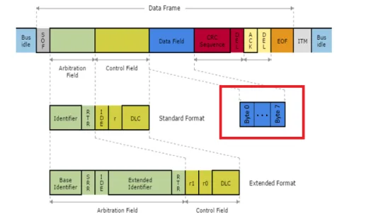
Data Detail Settings
Use [Data] → [Detail] to configure data information for each command entry.
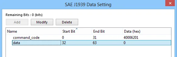
Device Address
| Bit/Word | Device Type | Format | Memo |
|---|---|---|---|
| B | Write_data (#local) | BOOL | When cycle time is set to 0, this address is triggered to send commands. |
| W | Command code | According to settings | |
| W | Data | According to settings |
Wiring Diagram
NOTE: The serial port pin assignments may vary between HMI models.
CANBus
| HMI | Direction | PLC |
|---|---|---|
| Pin assignments | CAN Bus Device | |
| CAN- | ↔ (bidirectional) | CAN- |
| CAN+ | ↔ (bidirectional) | CAN+ |
| GND | ↔ (bidirectional) | GND |
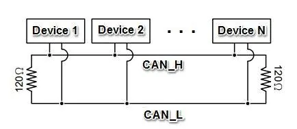
To minimize signal reflection on the CAN bus network, termination resistors should be installed at both ends of the network, as shown in the following figure.