Visual status indication is a common requirement in industrial automation. Operators rely on stack lights to quickly identify machine faults, production states, maintenance requests, and process alarms.
Consider a packaging machine on a production line. Under normal conditions, the machine runs without operator intervention. When issues occur, operators need immediate notification. Common fault conditions include:
- Low air pressure
- Product jam
- Emergency stop activation
- Motor overload
- Safety door open

A tower stack light provides instant visual feedback so operators can quickly identify machine conditions.
Example of a 5 stack:
| Light Color | Machine Status |
|---|---|
| Green | Machine Running |
| Amber | Warning Condition |
| Red | Alarm Condition |
| Blue | Maintenance Required |
| White | System Ready |
| Buzzer | Critical Alarm |

Software Required
- MapleLogic (PLC programming software)
Hardware Required
- Any Maple Systems PLC (a Micro PLC-FB1616P0202 is used in this example)
- Any Maple Systems TL1 Series Tower Stack Light (a TL160P2BF-5 is used in this example)
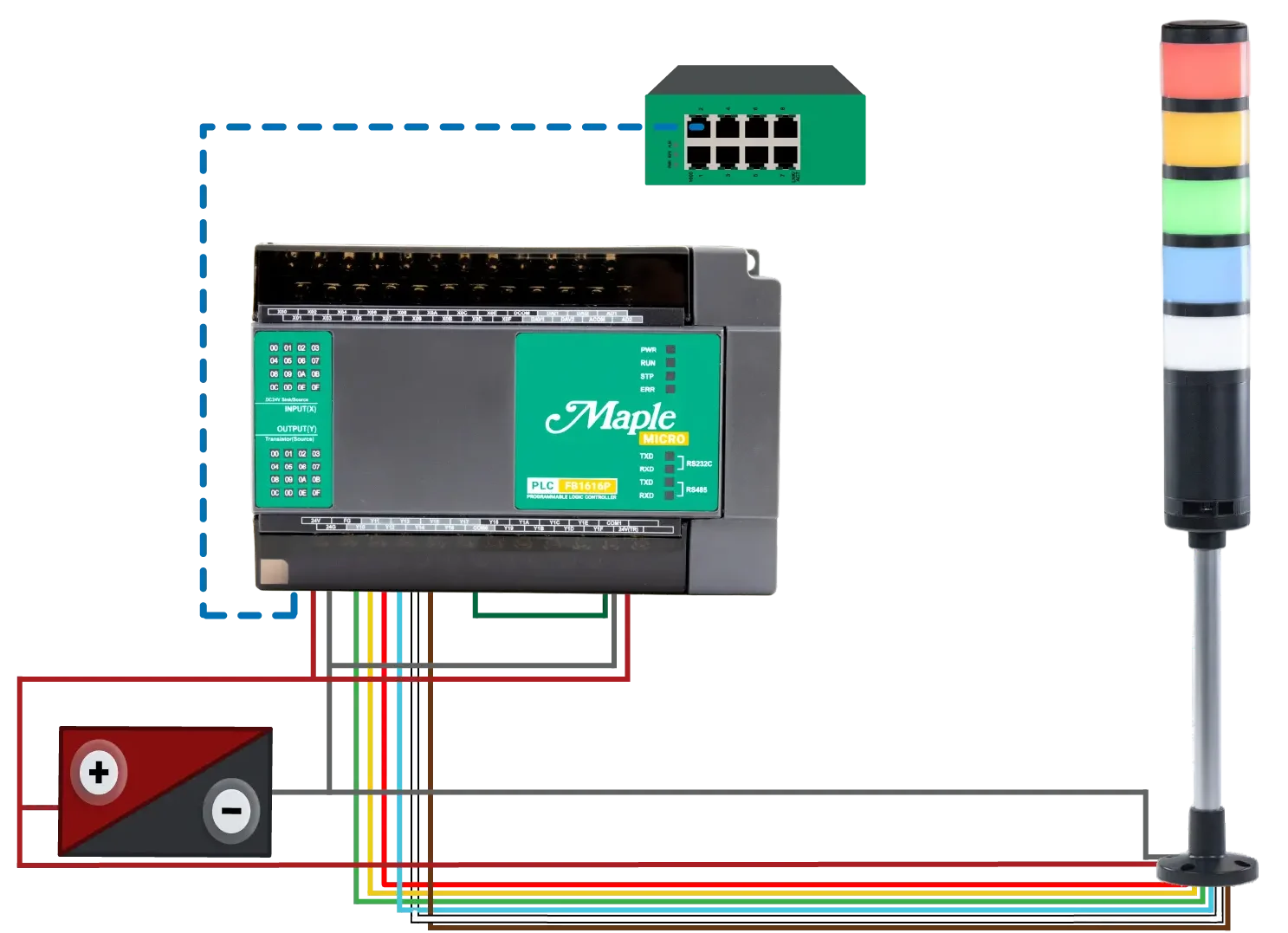
Network and Wiring Diagram

Diagram Description
This application uses a Maple Systems Micro PLC and a TL1 Series tower stack light. The PLC connects to a network switch through Ethernet, allowing communication with HMIs and other network devices. A 24 VDC power supply powers both the PLC and the stack light.
Connect the positive 24 VDC supply to the PLC’s 24V(TR) terminal. Connect the negative side to COM1 and jumper COM1 to COM0. The 24V(TR) terminal supplies power to the transistor outputs, while COM0 and COM1 provide the return path.
Digital Outputs:
- Y10 controls the green light
- Y11 controls the amber light
- Y12 controls the red light
- Y13 controls the blue light
- Y14 controls the white light
- Y15 controls the audible buzzer.
Each output connects directly to its corresponding stack light wire. When the PLC energizes an output, the associated light segment or buzzer activates.
PLC Configuration
This section walks through creating a new MapleLogic project and selecting the correct PLC hardware.

PLC Setup and Configuration in MapleLogic
Step by step guide on starting a new project using a Maple Systems Micro PLC in MapleLogic
Instructions: PLC Setup and Configuration in MapleLogic
Start a New Project in MapleLogic
- In MapleLogic, go to File > New Project
- Click the PLC-FB (Micro PLC)
- Click Next

Naming the Project
- Choose the correct CPU Type; for this example (PLC-FB1616)
- Name the project
- Click OK

New Ladder Diagram Program
- Right click on Program, click New Program
- Choose Scan for an LD Program
- Click OK

PLC Ladder Logic
The following ladder logic program was created in MapleLogic to control a five-color tower stack light and buzzer, providing clear visual and audible indication of machine operating states including System Ready, Machine Running, Warning, Maintenance Required, and Alarm conditions.

Building the Ladder Logic in MapleLogic
Step by step guide on configuring a ladder diagram program in MapleLogic
Instructions: Building the Ladder Logic in MapleLogic
Ladder Logic – Rung 1 – System Ready
- Rung 1 ladder logic for system ready (White)
- The first contact, X03 (SystemReady_Input), is a normally open contact, meaning it must be ON for the rung to be true.
- The next three contacts, X00 (Alarm_Input), X01 (Warning_Input), and X02 (Maintenance_Input), are normally closed contacts, meaning they must all be OFF for the rung to remain true.
The white light will turn on when the system is marked as ready, there is no alarm, there is no warning, and maintenance is not required.
Ladder Logic – Rung 2 – Machine Running
- Rung 2 ladder logic for machine running (Green)
- The rung uses four normally closed contacts: Alarm_Input (X00), Warning_Input (X01), Maintenance_Input (X02), and SystemReady_Input (X03).
- The logic is designed so that the green light turns on only when there is no active alarm, no warning, no maintenance request, and the system is not in the ready/idle state.
The machine is assumed to be actively running when all four of these inputs are OFF.
Ladder Logic – Rung 3 – Warning
- This ladder rung controls the Amber stack light (Y11) and represents the Warning condition.
- The rung consists of two contacts in series: Warning_Input (X01), which is a normally open contact, and Alarm_Input (X00), which is a normally closed contact.
- The logic is designed so that the amber light turns on whenever a warning condition is active, provided that an alarm condition is not active.
The amber light will illuminate when the system has a warning but no alarm. If both a warning and an alarm are present at the same time, the amber light will remain off because the alarm condition overrides it.
Ladder Logic – Rung 4 – Alarm
- This ladder rung controls the Red stack light (Y12) and represents the Alarm condition.
- The rung contains a single normally open contact, Alarm_Input (X00), connected directly to the Y12 (Red) output coil.
- Whenever the alarm input becomes active, the rung becomes true and energizes the red stack light. Unlike the warning and machine-running rungs, there are no additional conditions or interlocks in this rung. The red light is controlled solely by the alarm signal.
The red light serves as the highest-priority visual indication. As soon as an alarm condition occurs, the PLC turns on the red stack light to alert operators that immediate attention is required.
Ladder Logic – Rung 5 – Maintenance Required
- This ladder rung controls the Blue stack light (Y13) and represents the Maintenance Required condition.
- The rung contains two contacts connected in series: Maintenance_Input (X02), which is a normally open contact, and Alarm_Input (X00), which is a normally closed contact.
- The logic is designed so that the blue light turns on whenever maintenance is required, provided that there is no active alarm condition. This allows alarm status to take priority over maintenance status. If an alarm occurs, the normally closed alarm contact opens, preventing the blue light from turning on and allowing the red alarm indication to remain the highest-priority visual alert.
The blue light will illuminate when maintenance is needed and there is no active alarm. If both maintenance and alarm conditions occur at the same time, the blue light will remain off because the alarm condition overrides it.
Ladder Logic – Rung 6 – Buzzer
- This ladder rung controls the Buzzer output (Y15) and represents the Critical Alarm condition.
- The rung contains a single normally open contact, Alarm_Input (X00), connected directly to the Y15 (Buzzer) output coil.
- Whenever the alarm input becomes active, the rung changes to true and energizes the buzzer output. This means the buzzer operates in parallel with the red alarm light, providing an audible indication whenever an alarm condition occurs.
When an alarm is detected, the PLC will activate both the Red stack light (Y12) and the Buzzer (Y15). This combination provides both visual and audible notification so operators can quickly recognize a critical fault condition.
Downloading to the PLC
This section explains how to configure Ethernet communication settings, download the project to the PLC, and place the controller into RUN mode for online monitoring and testing.

Downloading the MapleLogic Project to the PLC
Step by step guide on downloading ethernet settings and the project to the PLC.
Instructions: Downloading the MapleLogic Project to the PLC
Configuring an IP Address to the PLC
- Click Parameter, then right click on PLC Parameter
- Click the Ethernet tab
- Set an IP Address to download to the PLC
- Click OK
You must configure the IP address in the PLC Parameters, download these settings to the PLC via USB. Then these settings are saved to the PLC. After the settings are saved you can download the PLC project via Ethernet.
Connect Option
- Go to Online
- Click Connect Option

Communication Setup – USB
- Click USB
- Click OK
Configure the communication setup to usb to download the ethernet settings to the Micro PLC.
Click Link+Download+Monitor
– Click Link+Download+MonitorDownload the ethernet settings to the PLC via USB download
Download Info Window
- check off Comment(Program)
- check off Variable Table
- Click OK to begin download process

Transmitting to the PLC
– Transmission process will begin to the PLC
Switch CPU to RUN Mode
– Click Yes to switch the CPU to RUN Mode
Project Online
- Project displaying that PLC is in RUN mode and OK
- Machine is running and Y10 is ON (green)

Live Simulation
Below is a live demonstration that showcases a Maple Systems Micro PLC controlling a TL1 Series tower stack light and audible buzzer through ladder logic programmed in MapleLogic. The video displays the PLC project online in monitor mode, allowing viewers to observe the ladder logic executing in real time while a live camera view shows the physical tower light responding to output changes.
To demonstrate the ladder logic, 24VDC is applied to each PLC input to simulate different machine status conditions. Applying 24V to X03 simulates the System Ready/Idle condition, causing the PLC to energize Y14 and illuminate the white stack light. With all inputs inactive, the PLC energizes Y10 to indicate the Machine Running state by turning on the green light. Applying 24V to X02 simulates a Maintenance Required condition, energizing Y13 and illuminating the blue light. Applying 24V to X01 simulates a Warning condition, causing the PLC to energize Y11 and turn on the amber light. Finally, applying 24V to X00 simulates a Critical Alarm, causing the PLC to energize Y12 and Y15 simultaneously, activating both the red stack light and the audible buzzer.
Recap
In this tutorial, you learned how to connect and program a Maple Systems Micro PLC to control a TL1 Series tower stack light and audible buzzer for machine status indication. Keep in mind that a Maple Systems Modular PLC can also be used. The guide covered the required hardware and software, wiring the tower light to the PLC outputs, configuring a new project in MapleLogic, creating ladder logic for operating states such as System Ready, Machine Running, Warning, Maintenance Required, and Alarm, and downloading the project to the PLC for testing. By combining visual and audible indicators with PLC logic, operators can quickly identify machine conditions and respond to events more efficiently.
Next Steps
Now that you have a basic tower stack light application running, consider expanding the project by integrating real machine signals such as safety circuits, fault conditions, maintenance counters, or production status indicators. You can also connect a Maple Systems HMI to display detailed alarm messages, operating statistics, and maintenance information alongside the tower light indications. As your application grows, implementing alarm acknowledgment, alarm history, and remote monitoring can provide operators and maintenance personnel with even greater visibility into machine performance and system health.
Sample Project
This integration tutorial uses this MapleLogic Sample Project
Resources & Documentation
The following guides and documentation are specific to the hardware used in this tutorial and will help with setup, configuration, and programming:
- MapleLogic User Manual
- Micro PLC User Manual
- PLC-FB1616P0202 Datasheet
- TL1 Quick Start Guide
- TL160P2BF-5 Datasheet
Looking for additional learning resources? Explore our library of tutorials, example projects, and software tools to help you get the most out of your system:
Also, browse our Support Center for a complete list of installation guides, FAQs, and additional technical documentation.
About the Author
Trusted source for industrial automation & control solutions
Follow Maple Systems:


