Introduction
All Maple Systems HMIs programmed with EBPro (EasyBuilder Pro), including every cMT X Series and cMT Series model, are compatible with a Siemens S7-1200/S7-1500 (Absolute Addressing) Ethernet. Configure your Controller and HMI/cMT with the following parameters to establish reliable communication.
Supported Series: Siemens S7-300/1200/1500 Series, ET200SP series
Website: http://www.siemens.com/entry/cc/en/
HMI Setting
| Parameters | Recommended | Options | Notes |
|---|---|---|---|
| PLC type | Siemens S7-1200/S7-1500 (Absolute Addressing) (Ethernet) | ||
| PLC I/F | Ethernet | ||
| Port no. | 102 | ||
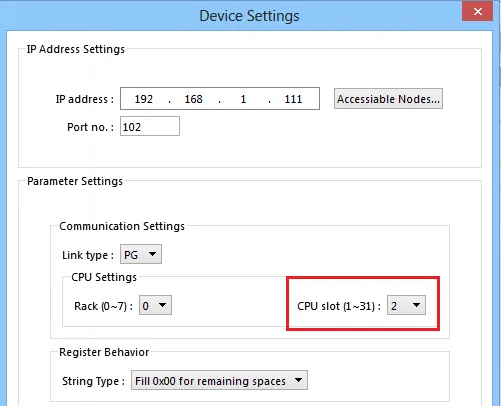
| Rack | 0 | ||
| CPU slot | 1 | ||
| On-line simulator | Yes | ||
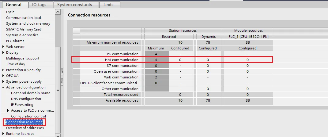
| Multi-HMI connect | TIA Settings *Note |
*Connect S7-300 settings
NOTE: According to Connection resource / HMI Communication settings
Support Device Type
| Data type | EasyBuilder data format | Memo |
|---|---|---|
| Bool | bit | |
| Byte | 16-bit BCD, Hex, Binary, Unsigned | 8-bit |
| SInt | 16-bit BCD, Hex, Binary, Signed | 8-bit |
| USInt | 16-bit BCD, Hex, Binary, Unsigned | 8-bit |
| Word | 16-bit BCD, Hex, Binary, Unsigned | 16-bit |
| Int | 16-bit BCD, Hex, Binary, Signed | 16-bit |
| UInt | 16-bit BCD, Hex, Binary, Unsigned | 16-bit |
| DWord | 32-bit BCD, Hex, Binary, Unsigned | 32-bit |
| DInt | 32-bit BCD, Hex, Binary, Signed | 32-bit |
| Real | 32-bit Float | 32-bit |
| UDInt | 32-bit BCD, Hex, Binary, Unsigned | 32-bit |
| LInt | 64-bit Signed | |
| ULInt | 64-bit Unsigned | |
| LReal | 64-bit Double | |
| Array |
NOTE1: EBPro (EasyBuilder Pro) V6.03.02 or later supports 64 bits data type, but please note that the address limit range is 48 bits in maximum.
NOTE2: Importing data types other than those in the above table may result in failure to communicate.
Both single-dimensional arrays and multi-dimensional arrays can start with non-zero values. Example: [1..9], or [1..3,2..5]
Address tags do not allow the use of special characters, such as: [ ] " etc., which may cause unexpected situations such as import exceptions or communication exceptions.
User Define Type
- User define type can be established in PLC data type.

2. User define type can be used in DB. User-defined types mapping address function are not supported. When using a user-defined type, please add it to the end of DB, to avoid influencing import and communication (address offset calculation).
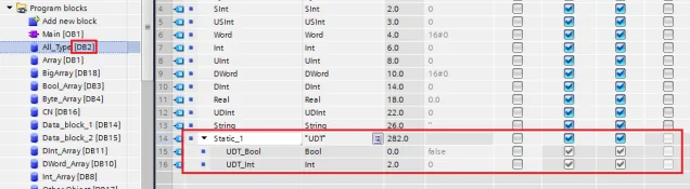
3. User define type cannot be imported automatically, you need to manually create an address in EBPro (EasyBuilder Pro) to communicate.
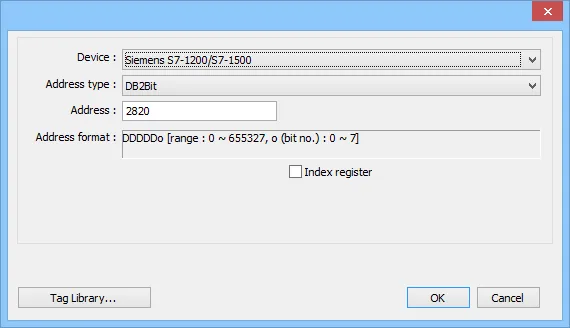
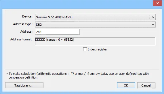
Device Address
| Bit/Word | Device type | Format | Range | Memo |
|---|---|---|---|---|
| B | I | DDDDDo | 0 ~ 655357 | Input (I) |
| B | Q | DDDDDo | 0 ~ 655357 | Output (O) |
| B | M | DDDDDo | 0 ~ 655357 | Bit Memory |
| B | DBnBit | FFFFFDDDDo | 0 ~ 6553599997 | |
| B | DBxBit | FFFFFDDDDDo | 0 ~ 10700655327 | |
| B | DB1Bit–DB99Bit | DDDDDo | 0 ~ 655357 | Data Register Bit |
| BYTE | IB | DDDDD | 0 ~ 65535 | Input (I) |
| W | IW | DDDDD | 0 ~ 65533 | Input (I) |
| DW | ID | DDDDD | 0 ~ 65535 | Input (I) |
| LW | IL | DDDDD | ||
| BYTE | QB | DDDDD | 0 ~ 65535 | Output (O) |
| W | QW | DDDDD | 0 ~ 65533 | Output (O) |
| DW | QD | DDDDD | 0 ~ 65535 | Output (O) |
| LW | QL | DDDDD | 0 ~ 65535 | |
| BYTE | MB | DDDDD | 0 ~ 65535 | Bit Memory |
| W | MW | DDDDD | 0 ~ 65533 | Bit Memory |
| DW | MD | DDDDD | 0 ~ 65535 | Bit Memory |
| LW | ML | DDDDD | 0 ~ 65535 | |
| BYTE | DBBn | FFFFFDDDD | 0 ~ 655359999 | Data Register |
| BYTE | DBBx | FFFFFDDDDD | 0 ~ 1070065535 | Data Register |
| W | DBn | FFFFFDDDD | 0 ~ 655359999 | Data Register |
| W | DBx | FFFFFDDDDD | 0 ~ 1070065535 | Data Register |
| DW | DBDn | FFFFFDDDD | 0 ~ 655359999 | Data Register |
| DW | DBDx | FFFFFDDDDD | 0 ~ 1070065535 | Data Register |
| LW | DBLx | FFFFFDDDDD | 0 ~ 1070065535 | |
| LW | DBLn | FFFFFDDDD | 0 ~ 599999999 | |
| W | DBn_String | FFFFFDDDD | 0 ~ 655359999 | Char Array |
| W | DBx_String | FFFFFDDDDD | 0 ~ 1070065535 | Char Array |
| W | DBn_String1 | FFFFFDDDD | 0 ~ 655359999 | String |
| W | DBx_String1 | FFFFFDDDDD | 0 ~ 1070065535 | String |
| DW | DBDn_String | FFFFFDDDD | 0 ~ 655359999 | Char Array |
| DW | DBDx_String | FFFFFDDDDD | 0 ~ 1070065535 | Char Array |
| W | DB1 ~ DB99 | DDDDD | 0 ~ 65535 | Data Register |
| DW | S5TIME_10Ms | FFFFFDDDD | 0 ~ 655359999 | 10MS ~ 9S990MS |
| DW | S5TIME_100Ms | FFFFFDDDD | 0 ~ 655359999 | 100MS ~ 1M39S900MS |
| DW | S5TIME_1S | FFFFFDDDD | 0 ~ 655359999 | 1S ~ 16M39S |
| DW | S5TIME_10S | FFFFFDDDD | 0 ~ 655359999 | 10S ~ 2H46M30S |
NOTE: Double word and floating point value must use DBDn device type.
NOTE: When using DBn, DBDn, DBLn, DBx, DBDx, DBLx addresses, the object address must be an even number due to the limitation of the original software protocol.
PLC Setting
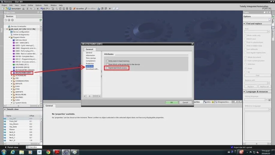
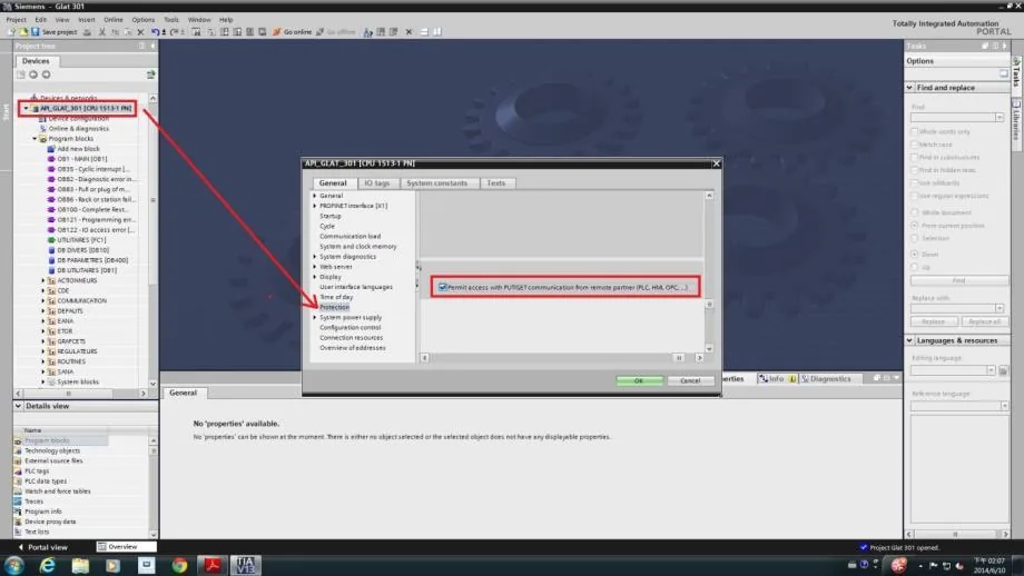
NOTE: Please follow the settings below, or the communication may fail.
- Do not check [DB UTILITAIRES] → [Attributes] → [Optimized block access].
2. Check [General] → [Protection] → [Permit access with PUT/GET communication from remote partner].
How to Import Address Tags Using TIA Portal
Exporting PLC Tags (.xlsx file format)
Open PLC Tags in TIA Portal
Under [PLC tags] create the address tags and then click the Export icon.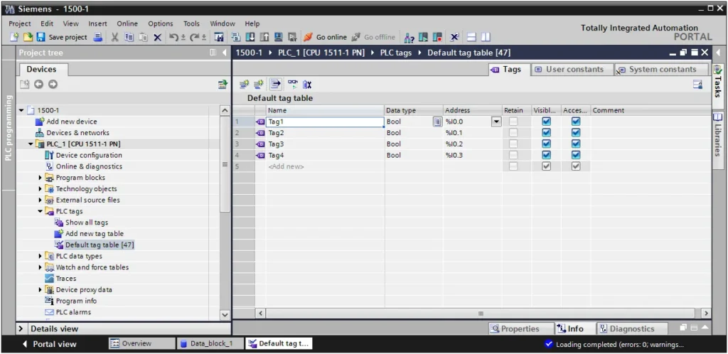
Designate Export Directory
Designate the directory to save the file and click OK.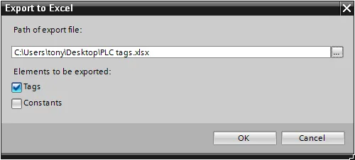
Exporting Program Blocks (.scl file format)
Create Data Block in TIA Portal
Under [Program blocks] createData_block_1 [DB1]as shown in the following figure. Click the right mouse button on [DB1] and then click [Generate source from blocks].![TIA Portal Program Blocks tree with Data_block_1 [DB1] selected under PLC_1 CPU 1511-1 PN.](https://media.maplesystems.com/wp-content/uploads/2026/06/12-tia-portal-program-blocks-data-block-selected-1024x767.webp "TIA Portal Program Blocks Data Block Selected")
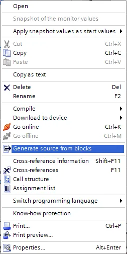
Add New PLC in EBPro (EasyBuilder)
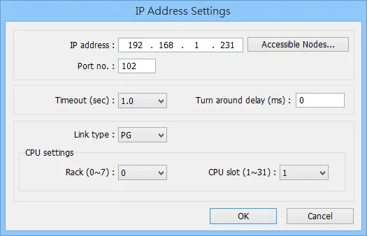
In EBPro (EasyBuilder) click [New PLC…], select Siemens S7-1500 (Ethernet) PLC type, and then click [Settings…] to set the parameters.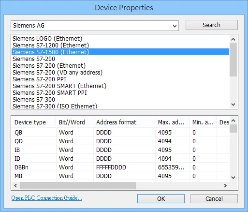
Importing Tags into EBPro (EasyBuilder)
Click Import Tag Button
Click [Import Tag…] button.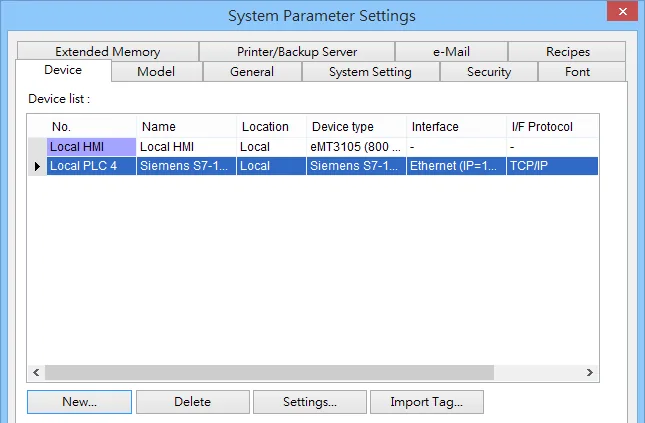
Select Import File Type
Select file type.scl; .dbor select TIA file*.apxxfor import (TIA File is recommended). Compiling the TIA file by using TIA software before import is necessary to avoid importing incomplete data.NOTE: Before importing TIA Files, users need to compile the file and download it to the PLC (*.ap12~17).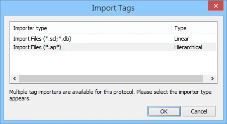
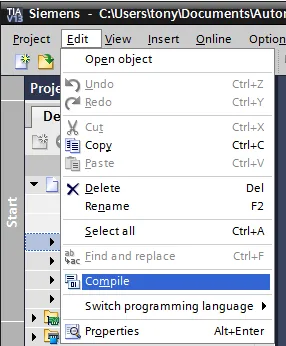
NOTE: CPU 1510SP-1 PN (6ES7510-1DJ01-0AB0) — unable to import using TIA project (*.ap*), please use [Get tag info] instead.
Import Files (*.scl; *.db)
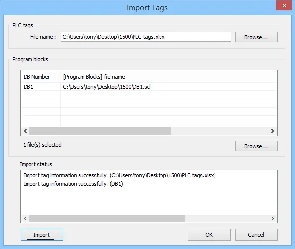
Select the PLC Tags and Program Blocks to be imported, click [Import] button, and then click [OK] to leave when the tags are imported successfully.
NOTE: At least one db file must be imported. If only plc tags are selected, import cannot complete successfully.
Import Files (*.ap*)
Select the tags to be imported and then click OK. (Support multiple devices in the same project)
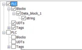
NOTE: Before importing the file, the editor needs to confirm that the TIA project is compiled and downloaded to the PLC and runs correctly.
The ‘Import tag information successfully’ message window is shown if the import has succeeded.
Get Tag Info
In S7-1200/1500 program software create PLC program and tag and then download
to PLC.Select Go offline, EBPro (EasyBuilder) will connect to PLC and get tag data. In PLC type select “SIEMENS S7-1200/1500 (Absolute Addressing) (Ethernet)”.Click “Settings…”, input PLC IP address
Click “Settings…”, input PLC IP addressCheck the PLC that is not connected to any PC. Click “Get Tag Info…”
Check the PLC that is not connected to any PC. Click “Get Tag Info…”Added Tag Manager that allows selecting the Siemens S7-1200/1500 PLC tags to be
imported.NOTE:
Both single-dimensional arrays and multi-dimensional arrays can start with non-zero values. Example: [1..9] , or [1..3,2..5]
Importing data types other than those in the above table may result in failure to communicate.
Address tags do not allow the use of special characters, such as: [ ] ” “,. etc., which may cause unexpected situations such as import exceptions or communication exceptions.
Create an object and click read address “Settings…”
Create an object and click read address “Settings…”In device select “S7-1200/1500” then select “user-defined tag”.
In device select “S7-1200/1500” then select “user-defined tag”.Select PLC tag.
Select PLC tag.
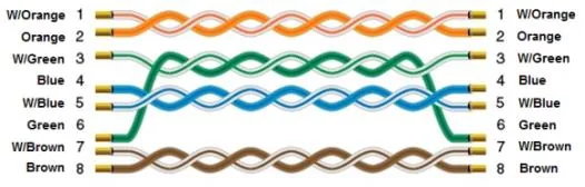
Wiring Diagram
The diagram below shows the Ethernet cable wiring.