Introduction
All Maple Systems HMIs programmed with EBPro (EasyBuilder Pro), including every cMT X Series and cMT Series model, are compatible with a Siemens S7-200 via Ethernet. Configure your Controller and HMI/cMT with the following parameters to establish reliable communication.
Supported Series: Siemens S7/200 Ethernet Series PLC (CPU212/214/215/216/221/222/224/226/226XM) with CP243-1 Ethernet module
Website: http://www.siemens.com/entry/cc/en/
HMI Settings
| Parameters | Recommended | Options | Notes |
|---|---|---|---|
| PLC type | SIEMENS S7-200 (Ethernet) | ||
| PLC I/F | Ethernet | ||
| Port no. | 102 | ||
| PLC sta. no. | 1 | 0–31 |
PLC Settings: S7/200 Ethernet Multi-Connection Settings
Step 1: Launching the Ethernet Wizard
Open Ethernet Wizard
In the Micro/WIN main menu, click Tools / Ethernet Wizard.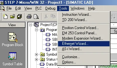
Advance Past Welcome Screen
Then, click Next.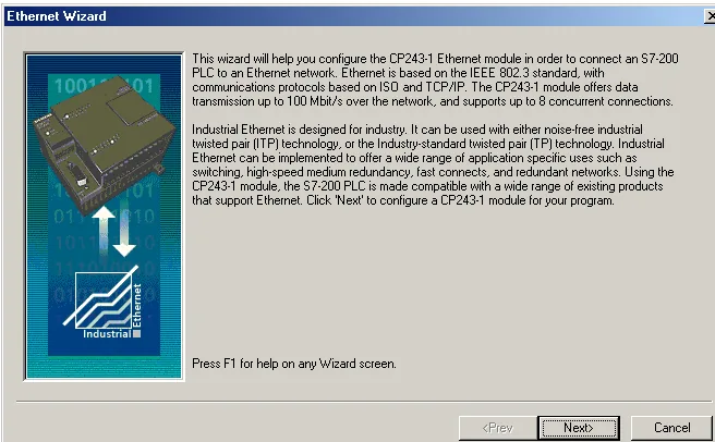
Confirm Symbolic Addressing Mode
Click Yes to proceed. This compiles the project and switches it to Symbolic Addressing Mode, which is required by the wizard.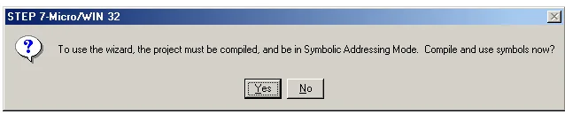
Step 2: Setting CP243-1 Module Position
Read Available Modules
Click Read Modules to search for installed CP243-1 Ethernet modules.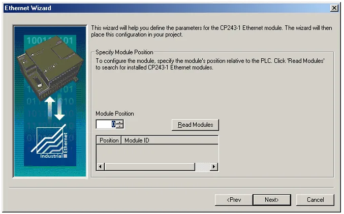
Select Ethernet Module and Advance
To view the results of Read Modules, select the Ethernet module. Click Next.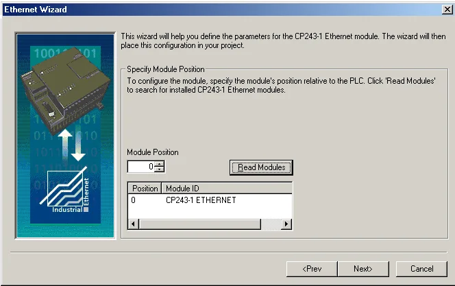
Step 3: Assigning Module Address
Set IP and Advance
Click Next to proceed past the Module Address screen, which allows you to assign an IP address, subnet mask, and gateway to the CP243-1 module.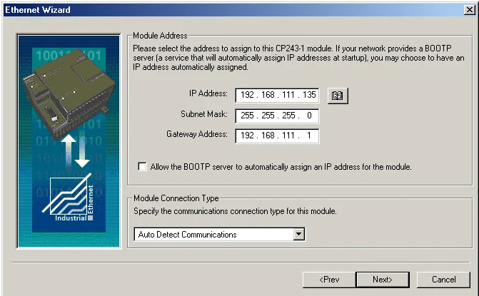
Set Number of Connections
Enter the number of desired available connections for this device. If 0 is entered, the only connection available will be the PG mode. The image below shows there are 4 connections for this module.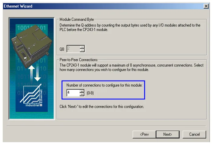
Configure Connection0 as Server
Connection0 — select This is a Server Connection. Notice the Local TSAP automatically incremented to10.00.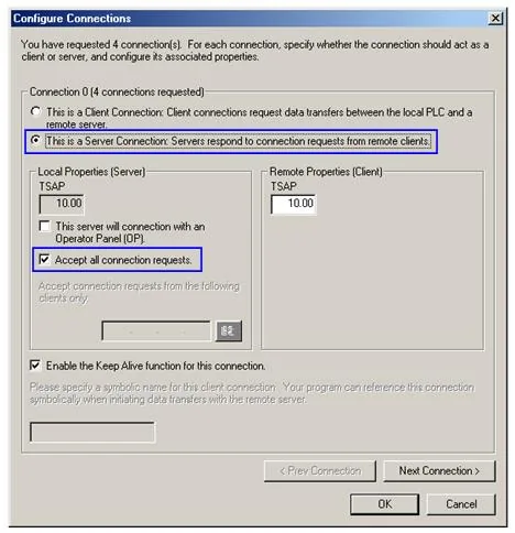
Configure Connection1 as Server
Connection1 — select This is a Server Connection. Notice the Local TSAP automatically incremented to11.00.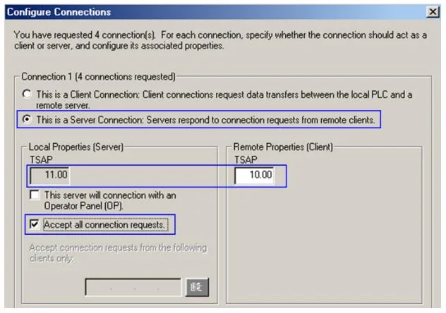
Set (EBPro) EasyBuilder TSAP Values
Upon completion of the settings above, set parameters in (EBPro) EasyBuilder. Set the value of Local TSAP here to the value of Remote TSAP in Micro/WIN and vice versa to realize multi-connection.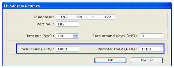
How to Import Tag
The tags created in the Symbol Table in Step7-MicroWIN software can be imported to EBPro (EasyBuilder).
Copy Tags from Symbol Table
In Symbol Table, create the tags. Select all the tags and click the right mouse button, then copy the tags.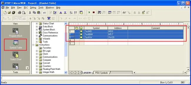
Open Import Tag in EBPro (EasyBuilder)
Launch EBPro (EasyBuilder), add the driver in the device list in System Parameter Settings, and then click the Import Tag button.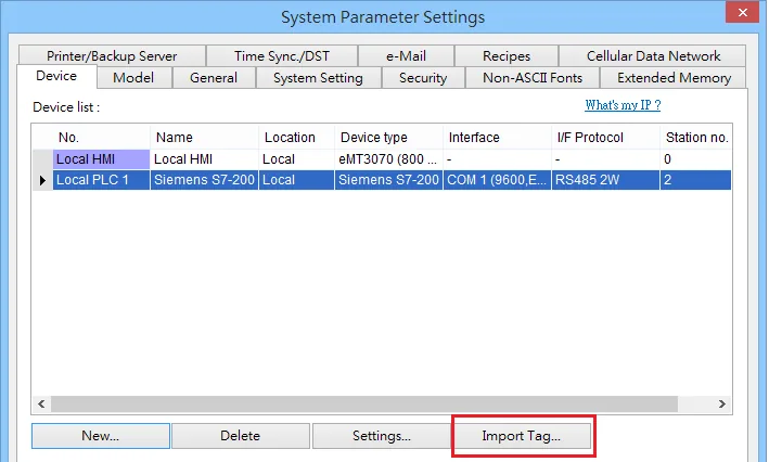
Paste Copied Tags
Paste the tags copied in step 1 and then click OK.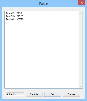
Select All Tags and Confirm
Select all the tags and then click OK.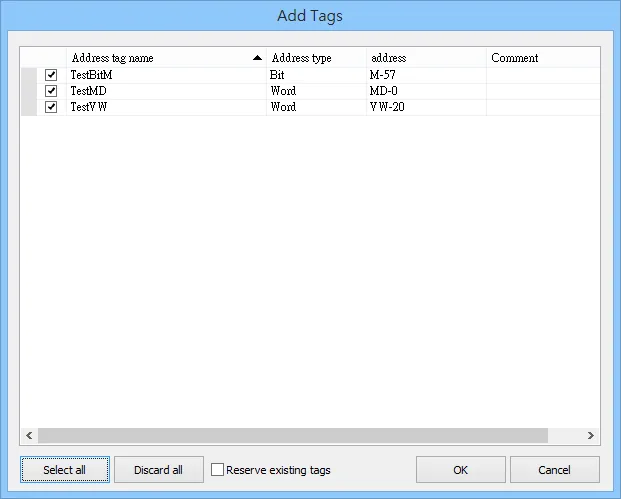
Verify Import Success
If the import succeeded, a confirmation message window appears.
Device Address
| Bit/Word | Device | Format | Range | Memo |
|---|---|---|---|---|
| B | I | DDDDo | 0 ~ 40957 | Input (I) |
| B | Q | DDDDo | 0 ~ 40957 | Output (O) |
| B | M | DDDDo | 0 ~ 40957 | Bit Memory |
| B | VW_Bit | DDDDDo | 0 ~ 102397 | V Memory Bit Address |
| B | S | DDDDo | 0 ~ 40957 | SCR |
| B | SM | DDDDo | 0 ~ 40957 | Special Memory |
| W | VW | DDDDD | 0 ~ 10239 | V Memory |
| DW | VD | DDDDD | 0 ~ 10239 | V Memory Double Word |
| W | VW_String | DDDDD | 0 ~ 10239 | String |
| DW | VD_String | DDDDD | 0 ~ 10239 | String |
| DW | MD | DDDDD | 0 ~ 10239 | Word Memory |
| Byte | VB | DDDDD | 0 ~ 10239 | V Memory Byte |
| Byte | SB | DDDDD | 0 ~ 10239 | SCR |
| W | SW | DDDDD | 0 ~ 10239 | SCR |
| DW | SD | DDDDD | 0 ~ 10239 | SCR |
| Byte | SMB | DDDDD | 0 ~ 10239 | Special Memory |
| W | SMW | DDDDD | 0 ~ 10239 | Special Memory |
| DW | SMD | DDDDD | 0 ~ 10239 | Special Memory |
NOTE: Double word and floating point values must use the VD device type.
Wiring Diagram
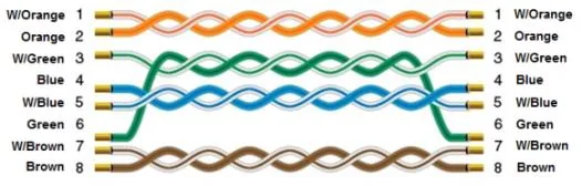
The diagram below shows the Ethernet cable wiring.