Introduction
All Maple Systems HMIs programmed with EBPro (EasyBuilder Pro), including every cMT X Series and cMT Series model, are compatible with Rockwell/Allen-Bradley PLC-5. Configure your Controller and HMI/cMT with the following parameters to establish reliable communication.
Website: https://www.rockwellautomation.com/
NOTE: Rockwell PLC5 driver uses CRC checksum.
HMI Settings
| Parameters | Recommended | Options | Notes |
|---|---|---|---|
| PLC type | Rockwell PLC5 | ||
| PLC I/F | RS232 | ||
| Baud rate | 19200 | 9600, 19200 | |
| Data bits | 8 | 8 | |
| Parity | Even | Even, Odd, None | |
| Stop bits | 1 | 1 | |
| HMI sta. no. | 0 | ||
| PLC sta. no. | 1 | 1–31 |
PLC Settings
Communication mode: DF1 Full Duplex protocol 19200, None, 8, 1 (default)
Allen-Bradley PLC-5 Family PLCs use DF1 Full Duplex protocol.
For PLC-5/10, PLC-5/15 and PLC-5/25, MT8000 should be connected to the DF1 port on the 1785-KE module.
For PLC-5/11, PLC-5/20, PLC-5/30 and PLC-5/40, MT8000 should be connected to the Channel 0 Port on the PLC.
Device Address
| Bit/Word | Device | Format | Range | Memo |
|---|---|---|---|---|
| B | I1 | DDDdd | 0 ~ 255 | 15 |
| B | O0 | DDDdd | 0 ~ 255 | 15 |
| B | B3 | DDDdd | 0 ~ 999 | 15 |
| B | B10 ~ 13 | DDDdd | 0 ~ 999 | 15 |
| B | S_Bit | DDDDDDdd | 0 ~ 255999 | 15 |
| B | Bfn | FFFDDDdd | 0 ~ 255999 | 15 |
| B | NfnBit | FFFDDDdd | 0 ~ 255999 | 15 |
| W | T4SV | DDD | 0 ~ 999 | Timer Preset Value (T4) |
| W | T4PV | DDD | 0 ~ 999 | Timer Accumulator Value (T4) |
| W | C5SV | DDD | 0 ~ 999 | Counter Preset Value (C5) |
| W | C5PV | DDD | 0 ~ 999 | Counter Accumulator Value (C5) |
| W | TfnSV | FFFDDD | 0 ~ 255999 | |
| W | TfnPV | FFFDDD | 0 ~ 255999 | |
| W | CfnSV | FFFDDD | 0 ~ 255999 | |
| W | CfnPV | FFFDDD | 0 ~ 255999 | |
| W | N7 | DDD | 0 ~ 999 | Integer data file (N7) |
| W | N10 ~ 15 | DDD | 0 ~ 999 | Integer data file (N10 ~ 15) |
| W | Nfn | FFFDDD | 0 ~ 255999 | Integer data file (V2.5.0 or newer) |
| W | S | DDD | 0 ~ 255 | |
| W | F8 | DDD | 0 ~ 999 | Floating point data file (F8) |
| W | Ffn | FFFDDD | 0 ~ 255999 | Floating point data file (V2.5.0 or newer) |
Wiring Diagram
NOTE: The serial port pin assignments may vary between HMI models.
RS-232 (9P D-Sub to 25P D-Sub: PLC5 CPU CH0)
| HMI | Direction | PLC |
|---|---|---|
| Pin assignments | AB CPU CH0 RS232 25P D-Sub Male | |
| Rx | ↔ (bidirectional) | 2 |
| Tx | ↔ (bidirectional) | 3 |
| GND | ↔ (bidirectional) | 7 |
Configuration Notes
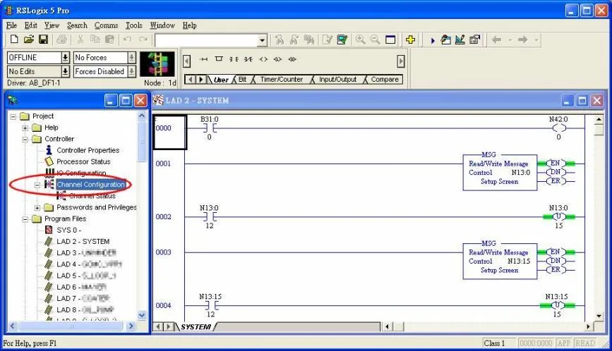
The default error checking of Rockwell/Allen-Bradley PLC5 is BCC, whereas our driver is CRC. Access Channel Configuration from RSLogix 5, under the Channel 0 tab, and select CRC for Error Detect.