Introduction
All Maple Systems HMIs programmed with EBPro (EasyBuilder Pro), including every cMT X Series and cMT Series model, are compatible with an Omron CJ/CS/CP Series (Ethernet – FINS/TCP). Configure your Controller and HMI/cMT with the following parameters to establish reliable communication.
Supported Series: OMRON CJ Series, CS Series, CP Series +Ethernet Module. (Ethernet FINS)
Website: http://www.omron.com/
NOTE: On initialization, switch from RUN MODE to MONITOR MODE.
HMI Settings
| Parameters | Recommended | Options | Notes |
|---|---|---|---|
| PLC type | OMRON CJ/CS/CP (Ethernet – FINS/TCP) | ||
| PLC I/F | Ethernet | ||
| Port no. | 9600 | ||
| PLC sta. no. | 0 |
PLC Settings
| Communication mode | Value |
|---|---|
| Communication mode | Ethernet (FINS/TCP) protocol |
Import Tags
Export the .cxr file from CX-Programmer
In CX-Programmer, go to Variables and export the*.cxrfile.Only addresses with a tag name can be imported; address type is required.
Open EBPro (EasyBuilder Pro) and set drive parameters
Open EBPro (EasyBuilder Pro) and set the drive parameters in System Parameter Settings, then click Import Tags.
Select the .cxr file
Browse to and select the*.cxrfile exported from CX-Programmer.Select the tags needed for the project
In the Add Tags dialog, check the tags that the project needs to use, then click OK.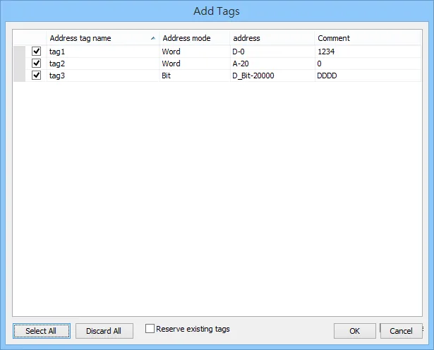
Confirm successful import
EBPro (EasyBuilder Pro) displays a confirmation that tag information was imported successfully.
Device Address
| Bit/Word | Device type | Format | Range | Memo |
|---|---|---|---|---|
| B | CIO_Bit | DDDDDdd | 0 ~ 3276715 | Channel I/O (CIO) |
| B | W_Bit | DDDDDdd | 0 ~ 3276715 | Work Area (WR) |
| B | H_Bit | DDDDDdd | 0 ~ 3276715 | Holding Area (HR) |
| B | A_Bit | DDDDDdd | 0 ~ 3276715 | Auxiliary Relay (AR) |
| B | D_Bit | DDDDDdd | 0 ~ 3276715 | Data Memory (DM) (Read only) |
| B | T_Bit | DDDDDdd | 0 ~ 3276715 | Timer (TIM) |
| B | C_Bit | DDDDDdd | 0 ~ 3276715 | Counter (CNT) |
| B | C_Flag | DDDD | 0 ~ 4095 | |
| B | T_Flag | DDDD | 0 ~ 4095 | |
| B | EM0_Bit ~ EM18_Bit | DDDDDdd | 0 ~ 3276715 | Extend Memory |
| W | CIO | DDDDD | 0 ~ 32767 | Channel I/O (CIO) |
| W | W | DDDDD | 0 ~ 32767 | Work Area (WR) |
| W | H | DDDDD | 0 ~ 32767 | Holding Area (HR) |
| W | A | DDDDD | 0 ~ 32767 | Auxiliary Relay (AR) |
| W | C | DDDDD | 0 ~ 32767 | Counter (CNT) (Read only) |
| W | T | DDDDD | 0 ~ 32767 | Timer (TIM) |
| W | D | DDDDD | 0 ~ 32767 | Data Memory (DM) |
| W | EM0 ~ EM18 | DDDDD | 0 ~ 32767 | Extend Memory |
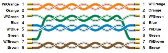
Wiring Diagram
The diagram below shows the Ethernet cable wiring.