Introduction
All Maple Systems HMIs programmed with EBPro (EasyBuilder Pro), including every cMT X Series and cMT Series model, are compatible with an Omron Ethernet PLC. Configure your Controller and HMI/cMT with the following parameters to establish reliable communication.
Supported Series: OMRON CJ Series, CS Series, CP Series +Ethernet Module. (Ethernet FINS)
Website: http://www.omron.com/
NOTE: On initialization, switch from RUN MODE to MONITOR MODE.
HMI Settings
| Parameters | Recommended | Options | Notes |
|---|---|---|---|
| PLC type | OMRON Ethernet | ||
| PLC I/F | Ethernet (UDP) | ||
| Port no. | 9600 | ||
| PLC sta. no. | 0 |
PLC Settings
| Setting | Value |
|---|---|
| Communication mode | Ethernet (UDP) protocol |
How to Connect OMRON NJ and NX Series
Open Built-in EtherNet/IP Port Settings
In the tree menu on the left-hand side, select Controller Setup » Built-in EtherNet/IP Port Settings.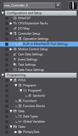
Set the FINS/UDP Port Number
Click the FINS button (marked in the red frame), and enter9600as the FINS/UDP port number. Select Automatic Generation as the conversion method.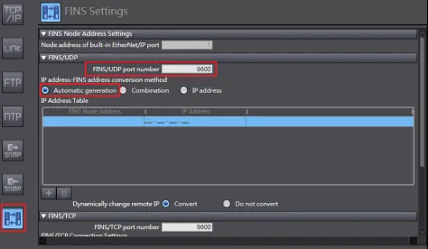
Select Global Variables
Select Global Variables to set the PLC address.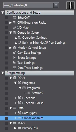
Configure Absolute Address Mapping
The AT column should be an absolute address mapping to Omron Ethernet.
Device Address
| Bit/Word | Device type | Format | Range | Memo |
|---|---|---|---|---|
| B | CIO_Bit | DDDDDdd | 0 ~ 3276715 | Channel I/O (CIO) |
| B | W_Bit | DDDDDdd | 0 ~ 3276715 | Work Area (WR) |
| B | H_Bit | DDDDDdd | 0 ~ 3276715 | Holding Area (HR) |
| B | A_Bit | DDDDDdd | 0 ~ 3276715 | Auxiliary Relay (AR) (Read Only) |
| B | D_Bit | DDDDDdd | 0 ~ 3276715 | Data Memory (DM) |
| B | T_Bit | DDDDDdd | 0 ~ 3276715 | Timer (TIM) |
| B | C_Bit | DDDDDdd | 0 ~ 3276715 | Counter (CNT) |
| B | C_Flag | DDDD | 0 ~ 4095 | |
| B | T_Flag | DDDD | 0 ~ 4095 | |
| B | EM0_Bit ~ EMC_Bit | DDDDDdd | 0 ~ 3276715 | Extend Memory Bit |
| B | CIO_Bit_Force | DDDDDdd | 0 ~ 3276715 | CIO Bit Force Command |
| W | CIO | DDDDD | 0 ~ 32767 | Channel I/O (CIO) |
| W | W | DDDDD | 0 ~ 32767 | Work Area (WR) |
| W | H | DDDDD | 0 ~ 32767 | Holding Area (HR) |
| W | A | DDDDD | 0 ~ 32767 | Auxiliary Relay (AR) (Read Only) |
| W | C | DDDDD | 0 ~ 32767 | Counter (CNT) |
| W | T | DDDDD | 0 ~ 32767 | Timer (TIM) |
| W | D | DDDDD | 0 ~ 32767 | Data Memory (DM) |
| W | EM0 ~ EMC | DDDDD | 0 ~ 32767 | Extend Memory |
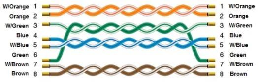
Wiring Diagram
The diagram below shows the Ethernet cable wiring.