Introduction
All Maple Systems HMIs programmed with EBPro (EasyBuilder Pro), including every cMT X Series and cMT Series model, are compatible with Beckhoff Embedded PC. Configure your Controller and HMI/cMT with the following parameters to establish reliable communication.
Supported Series: Intel-CX10x0, CX50x0 and TwinCAT
HMI Settings
| Parameters | Recommended | Options | Notes |
|---|---|---|---|
| PLC type | Beckhoff Embedded PC | ||
| PLC I/F | Ethernet | ||
| Port no. | 48898 | ||
| ADS port | 801 | 801, 811, 821, 831 | |
| PLC sta. no. | 1 |
PLC Setting
For TwinCAT
Confirm PC IP Address
Confirm PC IP address.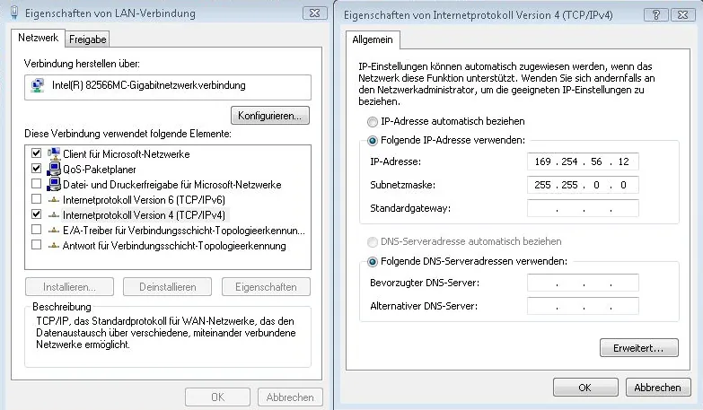
Open TwinCAT Set IP Address
Open TwinCAT, set IP address169.254.56.12.1.1.Build TwinCAT Route Table
Use TwinCAT to build a Route Table to make sure the system is connected. If PLC power turns OFF and then ON, please redo this step.When connected, if u0022Xu0022 is displayed, the connection succeeded.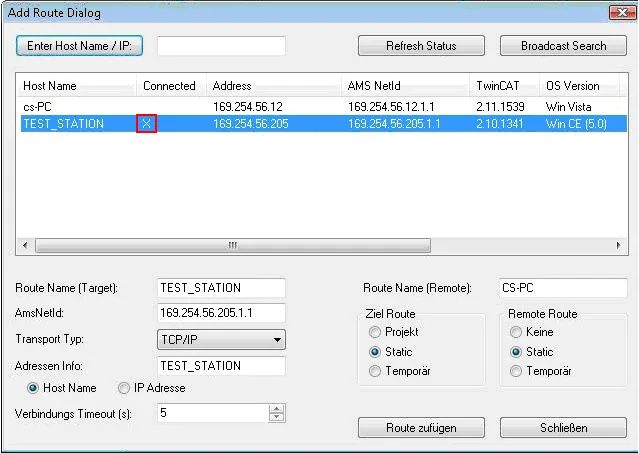
Configure EBPro (EasyBuilder) Network Settings
Open EBPro (EasyBuilder), set IP address, ADS port and Port no.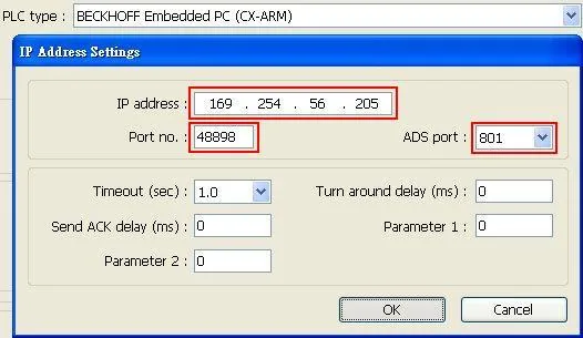
Run Online Simulation
Run online simulation.Note: If the project is downloaded to HMI, please set HMI IP169.254.56.12identically to TwinCAT IP address setting.
For CERHOST
Launch CERHOST Connect to PLC
ExecuteCERHOST.exeto connect with PLC on PC.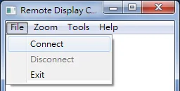
Enter PLC IP and Password
Enter PLC IP and Password (default password:1).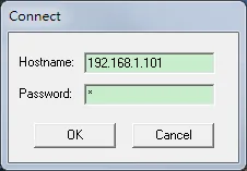
Open Control Panel via Start
Succeeded to connect with PLC, click Start; click Control Panel.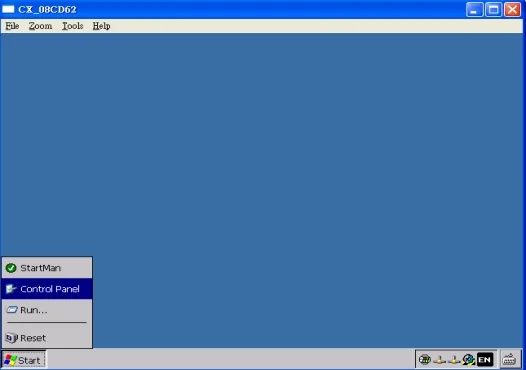
Check PLC IP via Network Connections
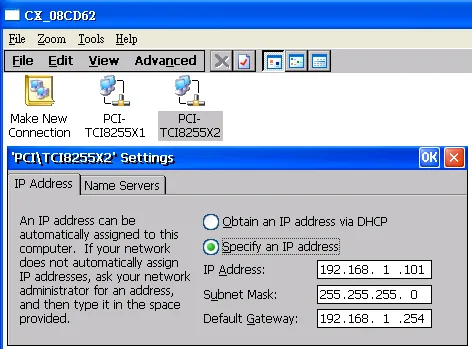
Click [Network and Dial-Up Connections] to display PLC device information; select the PLC to check its IP.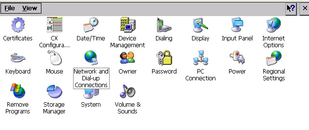
Execute TcAmsRemoteMgr from System
Access PLC system settings, the default directory:u005cHard Disku005cSystem, execute [TcAmsRemoteMgr].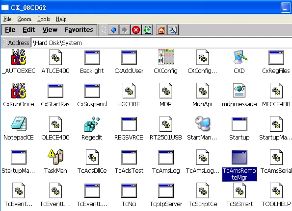
Add HMI to AMS Remote Connections
AMS Net Id consists of 6 numbers, separated by u0022.u0022. The first 4 numbers stand for IP and followed by u00221.1u0022. Click [Add] to add the HMI and click [OK] to finish setting.nn- Name: Device name.n- AMS Net Id: The IP followed by u00221.1u0022 of the device to connect with.n- Address: The IP address of the device to connect with.n- Transport: The way of connection.n- Slow Connection: As shown in the figure below.Verify PLC AMS Net ID
Return to Control Panel; execute CX Configuration Tool to confirm PLC AMS Net Id.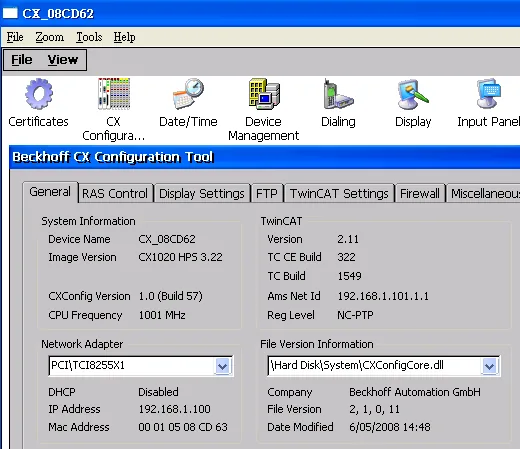
Reset PLC to Apply Settings
Confirm settings and click Start; Reset PLC.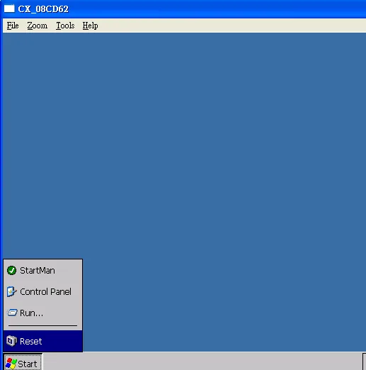
Building Data Structure
Create STRUCT Data Types
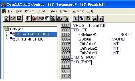
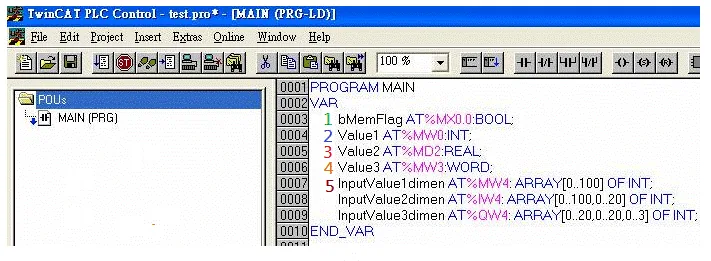
This driver supports variables under STRUCT structure. Click [Data Type] to open Structure Editor and create the same [Name] and [Data Type] as in TwinCAT PLC Control. The standard data types include:BOOL,WORD,INT,UINT,DINT,UDINT,REAL,DWORD,ARRAYnnThe syntax of Tag in TwinCAT software is: Tag Name + AT + % + Type, as shown in the following figure.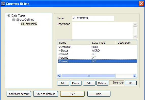
Rebuild TwinCAT Project
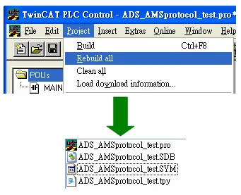
Project; Rebuild all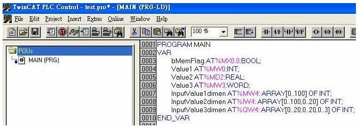
Set PLC IP in EBPro (EasyBuilder)
Set PLC IP in EBPro (EasyBuilder).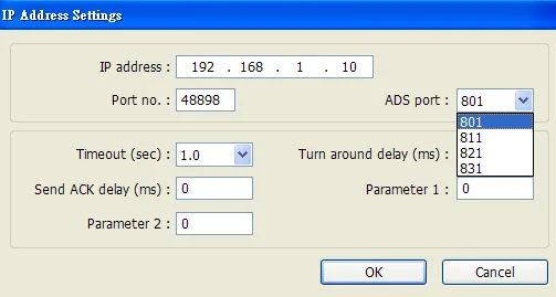
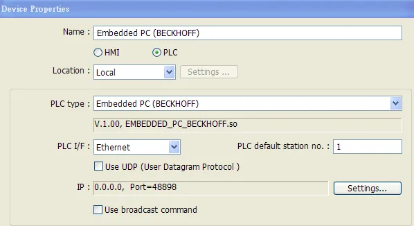
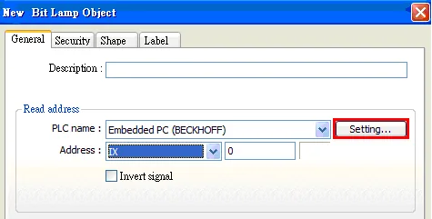
Import TPY Tags into EBPro (EasyBuilder)
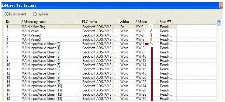
Click [Import Tag] button in EBPro (EasyBuilder) to open the.tpyfile compiled by TwinCAT PLC Control.nnImport.tpyto EasyBuilder, the result is shown in the following figure.When using Beckhoff driver, if the TPY file cannot be imported, try to download and install MSXML 4.0 from Microsoft Download Center.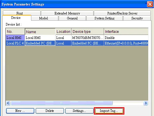
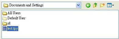
Select Tags to Import
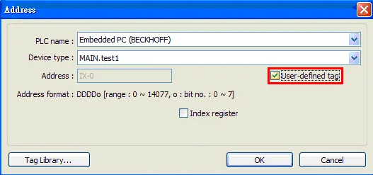
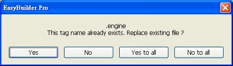
The following dialog box appears for users to select all or part of the data to import. A reminding message is shown when importing the same data repeatedly.EZware/EZwarePlus (EasyBuilder8000) does not support [Comment] setting.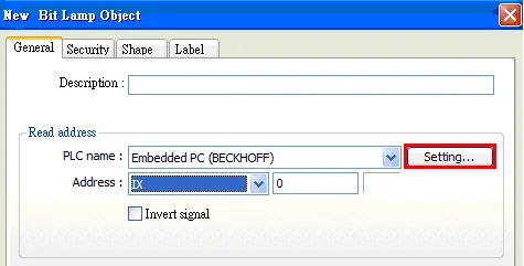

Download Project to HMI
Download the project compiled in EBPro (EasyBuilder) to HMI.
Device Address
| Bit/Word | Device Type | Format | Range | Memo |
|---|---|---|---|---|
| B | IX | DDDDDo | 0 ~ 655357 | o : Bit no.(0 ~ 7) |
| B | QX | DDDDDo | 0 ~ 655357 | o : Bit no.(0 ~ 7) |
| B | MX | DDDDDo | 0 ~ 655357 | o : Bit no.(0 ~ 7) |
| W | IW | DDDDD | 0 ~ 65535 | |
| W | QW | DDDDD | 0 ~ 65535 | |
| W | MW | DDDDD | 0 ~ 65535 | |
| DW | ID | DDDDD | 0 ~ 65535 | |
| DW | QD | DDDDD | 0 ~ 65535 | |
| DW | MD | DDDDD | 0 ~ 65535 |
Support Device Type
| Data Type | EBPro (EasyBuilder) Data Format | Memo |
|---|---|---|
| Bool | bit | |
| Word | 16-bit BCD, Hex, Binary, Unsigned | 16-bit |
| Int | 16-bit BCD, Hex, Binary, Signed | 16-bit |
| UInt | 16-bit BCD, Hex, Binary, Unsigned | 16-bit |
| DWord | 32-bit BCD, Hex, Binary, Unsigned | 32-bit |
| DInt | 32-bit BCD, Hex, Binary, Signed | 32-bit |
| Real | 32-bit Float | 32-bit |
| UDInt | 32-bit BCD, Hex, Binary, Unsigned | 32-bit |
| String | ASCII input and ASCII display |
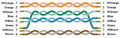
Wiring Diagram
The diagram below shows the Ethernet cable wiring.