
Implementing a Maple Systems HMI with a Schneider Electric Modicon PLC is straightforward using the built-in Schneider PLC protocols available in EBPro. No additional communication hardware or gateways are required. First, connect both devices to the same Ethernet network and configure their IP addresses. Then, establish communication in just a few steps.
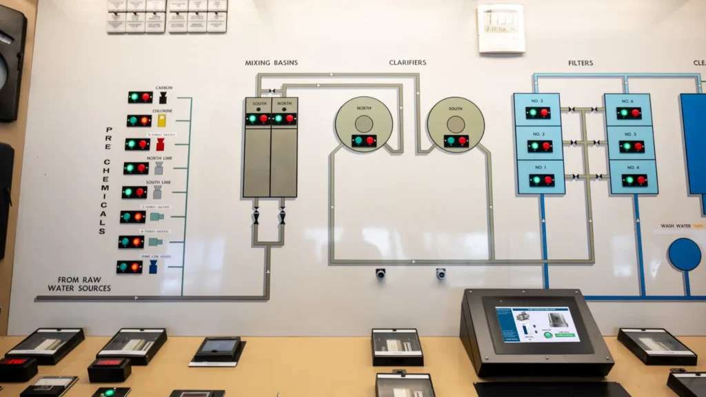
For example, in a municipal water treatment plant, the M241 PLC controls pumps, valves, chemical dosing systems, and storage tank levels. Meanwhile, the Maple Systems HMI provides operators with a centralized interface to monitor process data, acknowledge alarms, and control equipment.
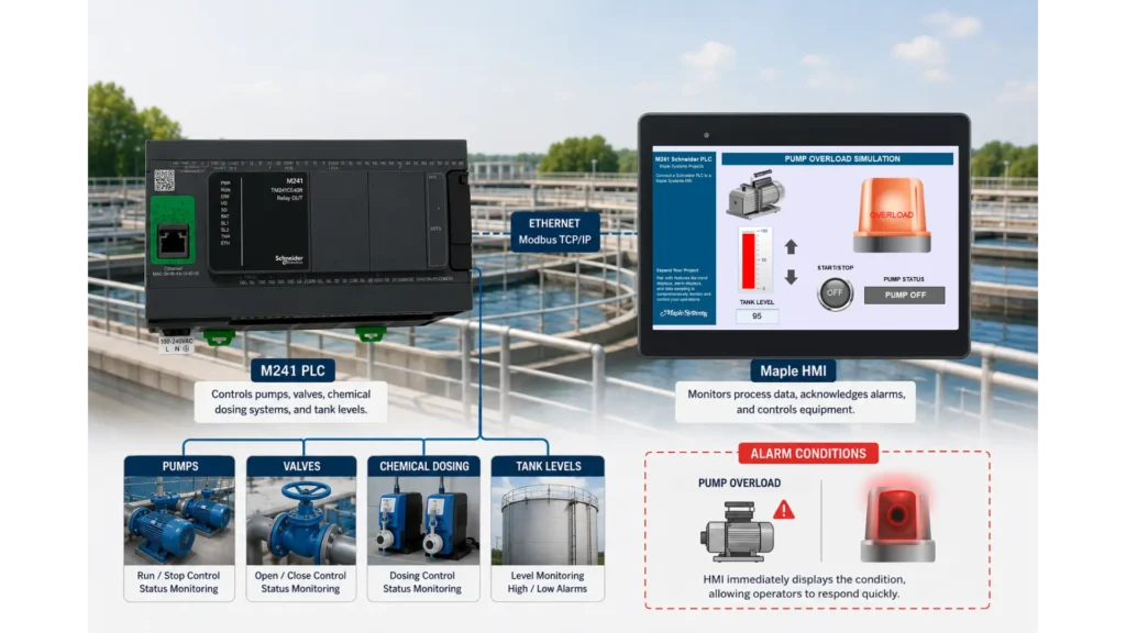
If a high-level tank alarm, pump overload, or communication fault occurs, the HMI immediately displays the condition. As a result, operators can identify the issue quickly, respond faster, and keep the treatment process running safely and efficiently.
Software Required
- EBPro (Required software for any Maple Systems HMI)
- EcoStruxure Machine Expert Logic Builder (software for a Schneider Modicon M241 PLC)
Hardware Required
- Any Maple Systems HMI (cMT2078Xv2 is used in this example)
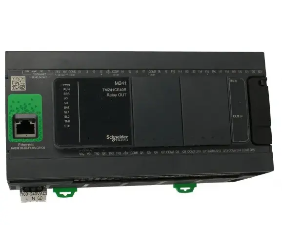
- Schneider PLC (A Modicon M241 TM241CE40R Controller is used in this example)
Network Diagram
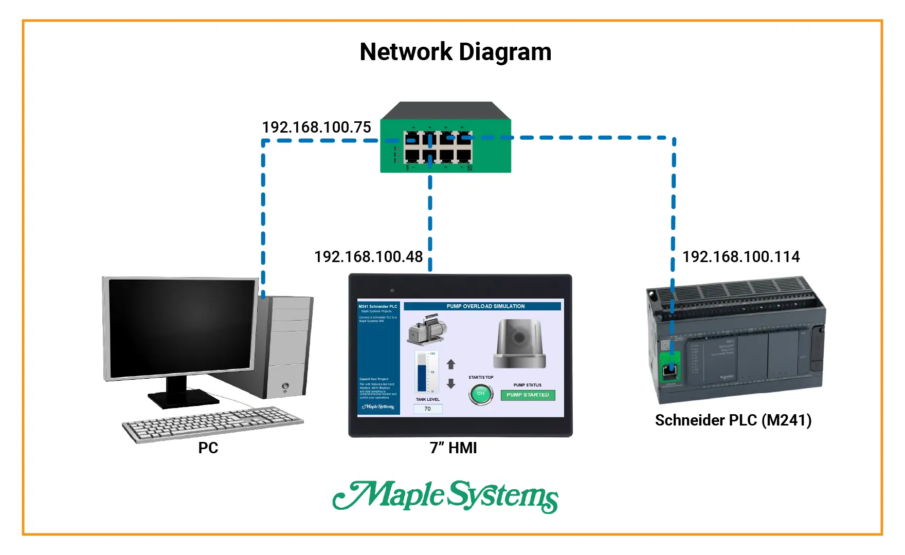
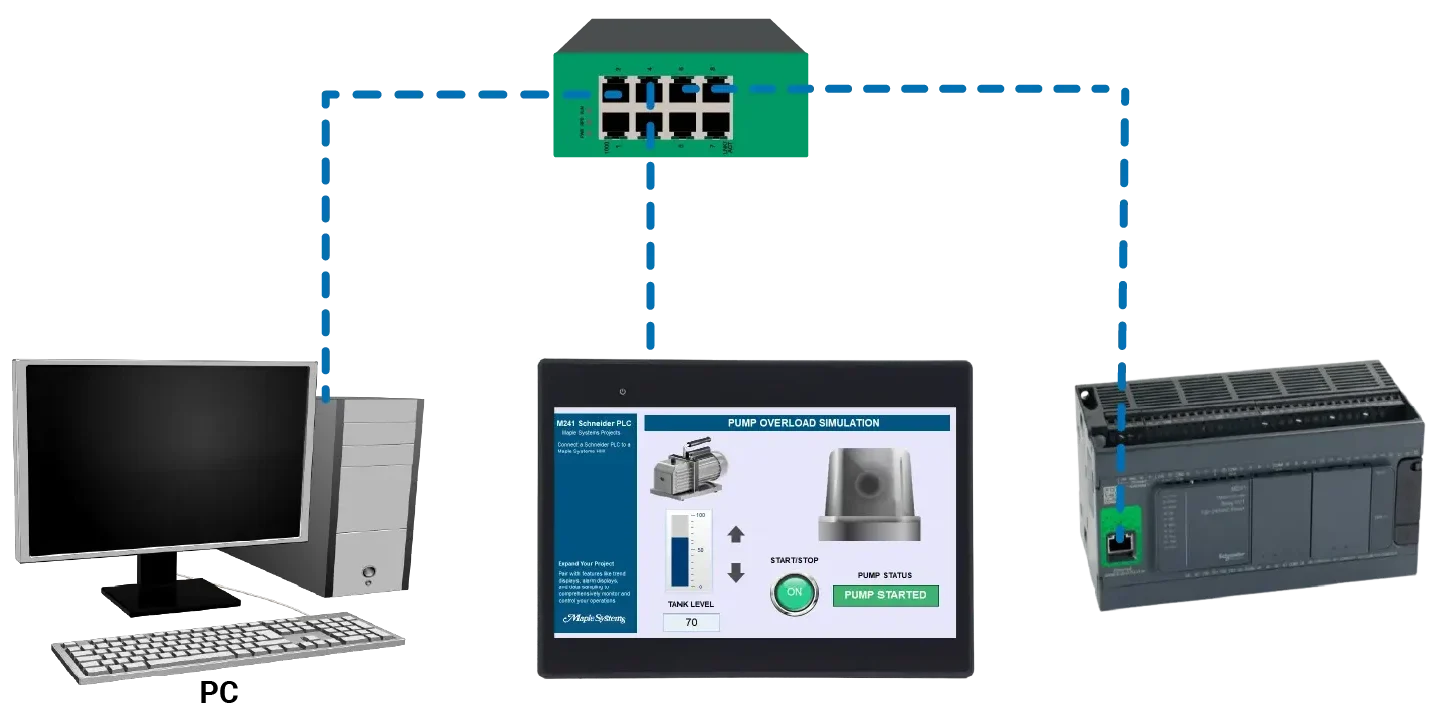
This network diagram shows an Ethernet network connecting a PC, Maple Systems HMI, and Schneider M241 PLC. All three devices connect to the same Ethernet switch. They also share the same subnet, allowing them to communicate reliably.
The PC (192.168.100.75) programs and configures both the HMI in EBPro and the PLC in EcoStruxure Machine Expert Logic Builder. Meanwhile, the Maple Systems HMI (192.168.100.48) gives operators a central interface to monitor and control the application.
The Schneider M241 PLC (192.168.100.114) controls the field I/O and machine logic. The HMI and PLC communicate over Ethernet using the Schneider Modbus TCP/IP protocol. As a result, the HMI can read PLC data, write commands, and display real-time system status.
PLC Configuration and Logic Build
This section explains how to configure the Schneider Electric M241 PLC, establish Ethernet communication, create the program structure, and build the ladder logic used for the pump-control application.

Schneider PLC Software Setup and Ladder Logic Build
The following steps show how to create a new project for a Schneider Electric Modicon M241 TM241CE40R, configure Ethernet communication, add a ladder-logic POU, define variables, and build the pump-control logic shown in the images.
Instructions: Schneider PLC Software Setup and Ladder Logic Build
Create the New Project
- Open EcoStruxure Machine Expert Logic Builder 2.6, then select File > New Project
- Select Default Project
- Set the controller to TM241CE40R (Schneider Electric)
- Select the controller firmware version that matches the physical PLC. The example uses 5.5.14.17
- Enter a controller name, such as M241 for this example
- Set the language for SR_Main to Ladder Logic Diagram (LD)
- Enter the project name and choose the folder where the project will be saved
- Select OK
The software creates the controller application, a global variable list, the defaultSR_Mainprogram, and the MAST task configuration. The firmware selected in the project should match the firmware installed in the PLC. A mismatch may prevent the project from logging in or downloading correctly.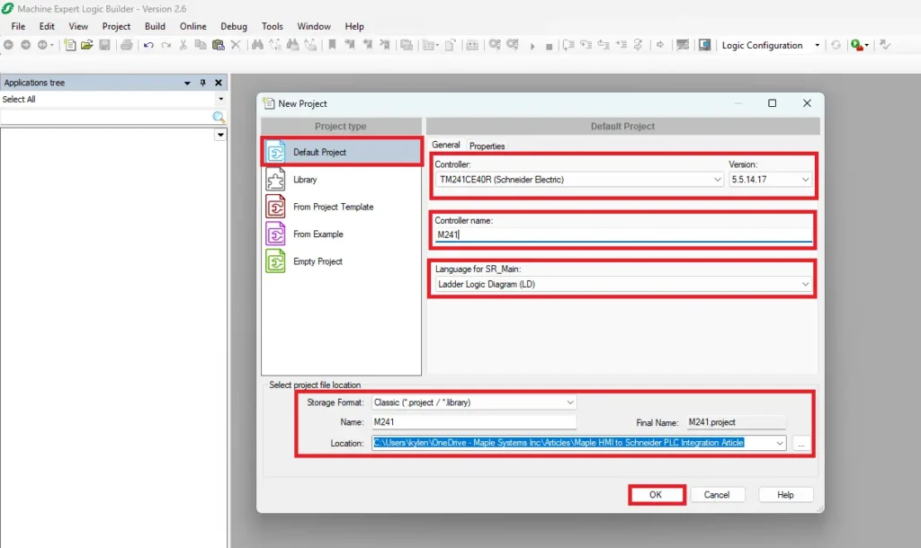
Configure the Communication Settings
- After the project opens, select the M241 controller in the Applications tree
- Open the Communication Settings tab. The detected controller appears in the communication list
- In the example, the controller is found at:
IP address: 192.168.100.114
Controller: TM241CE40R
Firmware: 5.5.14.17
- Set Connection Mode to IP Address.
- Select Test to verify communication
- Confirm that the controller appears in the device list without a communication error
For this example, the PC you are using must have an address on the same subnet. For example, the computer could use192.168.100.10with a subnet mask of255.255.255.0.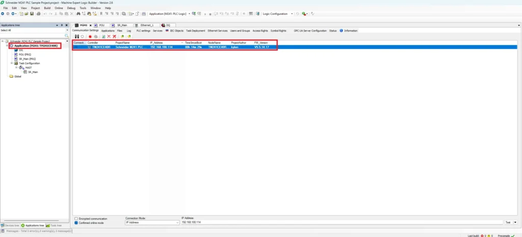
Configure the PLC Ethernet Address
- Switch from the Applications tree to the Devices tree
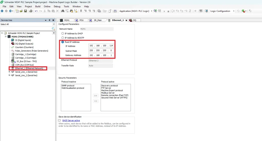
- Expand the M241 controller and select: Ethernet_1 (Ethernet Network)
- Under Configured Parameters, select Fixed IP Address and enter the settings shown below:
IP address 192.168.100.114
Subnet mask 255.255.255.0
Gateway address 192.168.100.1 (may not need)
The gateway is normally the address of the router. A gateway may not be required when the PLC, HMI, and PC only communicate on the same local subnet.
The important setting for communication with a Maple Systems HMI is Modbus Server, which allows the HMI to access mapped PLC variables through Modbus TCP/IP.
After changing the Ethernet settings, rebuild and download the project to the controller. A controller restart may be required before the new address becomes active.
Adding a POU Program
A POU, or Program Organization Unit, contains the PLC program logic.
- Right-click Application (M241: TM241CE40R)
- Select Add Object
- Select POU
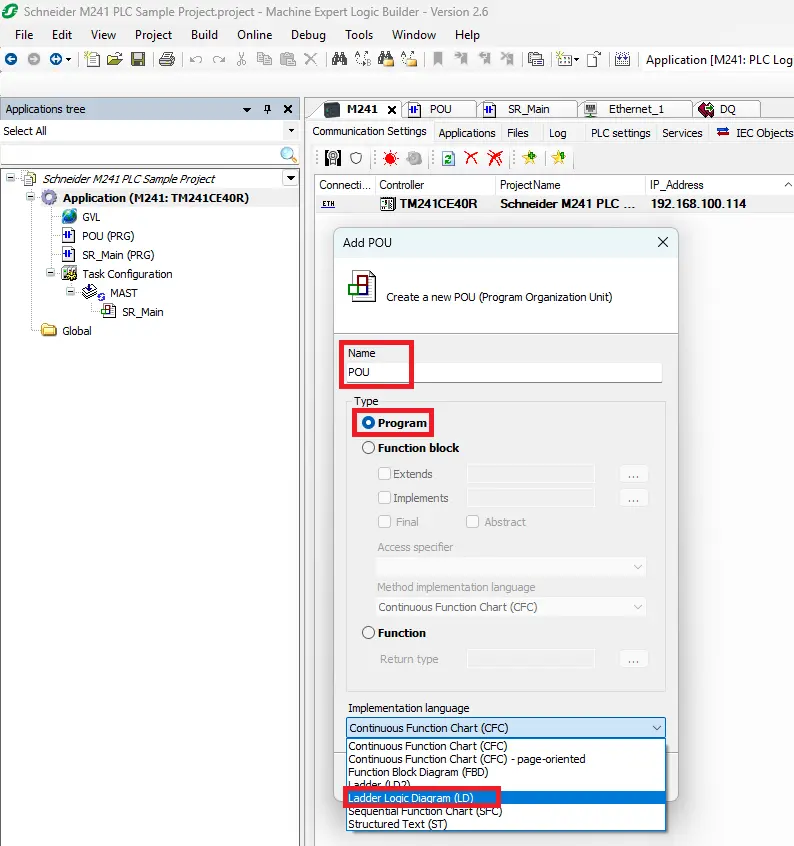
- In the Add POU window: Enter a name such as POU
- Select Program as the POU type
- Set the implementation language to Ladder Logic Diagram (LD)
The newPOU (PRG)appears under the application.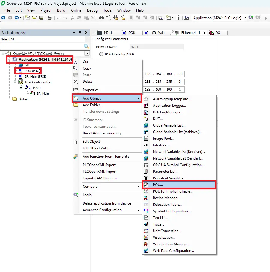
Calling the POU in the Main Program Ladder Logic
The new POU must be scheduled before the PLC can execute it
- In Ladder, it appears as a Program Call block, not a normal output coil or function block. Schneider refers to this as calling a Program POU from another Program POU
The POU executes whenever power flows to the block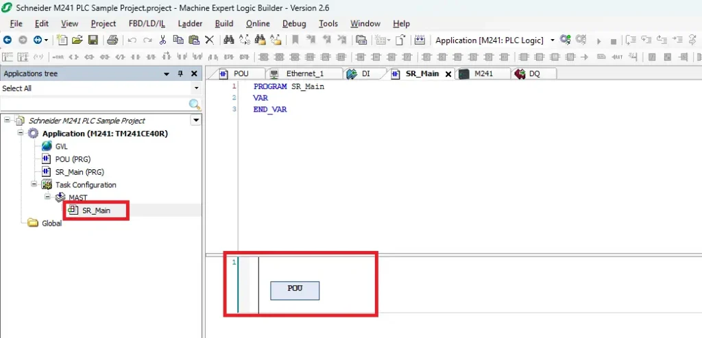
Add the Program Variables
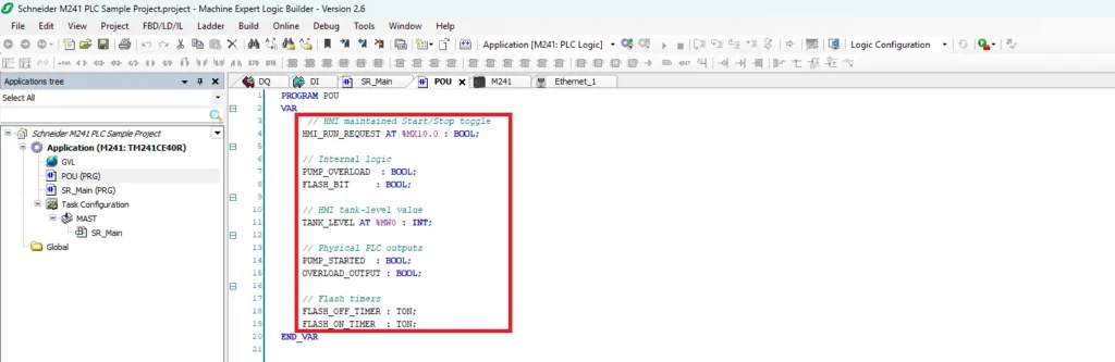
- Open the new POU and enter the variables in the declaration section above the ladder editor.
- The following can be copy and pasted into the program for this project
PROGRAM POU
VAR
// HMI maintained Start/Stop toggle
HMI_RUN_REQUEST AT %MX10.0 : BOOL;
// Internal logic
PUMP_OVERLOAD : BOOL;
FLASH_BIT : BOOL;
// HMI tank-level value
TANK_LEVEL AT %MW0 : INT;
// Physical PLC outputs
PUMP_STARTED : BOOL;
OVERLOAD_OUTPUT : BOOL;
// Flash timers
FLASH_OFF_TIMER : TON;
FLASH_ON_TIMER : TON;
END_VAR
Variable descriptions
HMI_RUN_REQUEST AT %MX10.0 : BOOL;
This Boolean variable receives the maintained Start/Stop command from the Maple Systems HMI. The HMI writes to memory bit %MX10.0.
PUMP_OVERLOAD : BOOL;
This internal Boolean becomes true when the tank level reaches the overload threshold.
FLASH_BIT : BOOL;
This internal bit alternates between true and false to create the flashing alarm signal.
TANK_LEVEL AT %MW0 : INT;
This integer stores the tank-level value. The HMI reads or writes the value through memory word %MW0.
PUMP_STARTED : BOOL;
This Boolean represents the pump-running output or pump-running status.
OVERLOAD_OUTPUT : BOOL;
This Boolean represents the flashing overload output.
FLASH_OFF_TIMER : TON; and FLASH_ON_TIMER : TON;
These are on-delay timer instances used to alternate the alarm output every second.
If PUMP_STARTED and OVERLOAD_OUTPUT control physical terminals, map them to the correct M241 digital outputs in the I/O Mapping window or assign direct output addresses such as %QX0.0 and %QX0.1.
Add the Ladder Logic
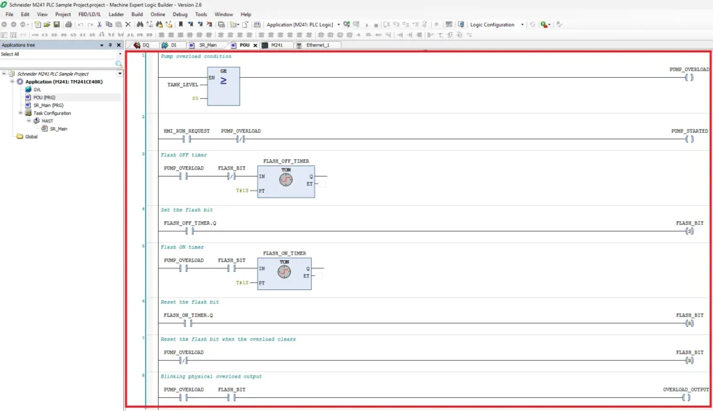
The ladder program contains eight networks.
Network 1: Detect the Pump Overload Condition
Insert a GE, or greater-than-or-equal comparison block.
Configure it as:
- TANK_LEVEL >= 85
- Connect the comparison result to the PUMP_OVERLOAD coil.
This network turns on PUMP_OVERLOAD when the tank level reaches or exceeds 85.
Network 2: Control the Pump-Started Output
Add:
- A normally open HMI_RUN_REQUEST contact.
- A normally closed PUMP_OVERLOAD contact.
- A standard PUMP_STARTED coil.
The pump runs when the HMI run request is active and no overload condition exists. When the tank level reaches 85, PUMP_OVERLOAD opens the interlock and turns the pump output off.
Network 3: Start the Flash-Off Timer
Add:
- A normally open PUMP_OVERLOAD contact.
- A normally closed FLASH_BIT contact.
- A TON block using FLASH_OFF_TIMER.
- Set the preset time to T#1S.
This timer runs while the overload is active and FLASH_BIT is false.
Network 4: Set the Flash Bit
Add:
- A normally open FLASH_OFF_TIMER.Q contact.
- A Set coil for FLASH_BIT.
- After the first timer reaches one second, the network sets FLASH_BIT.
Network 5: Start the Flash-On Timer
Add:
- A normally open PUMP_OVERLOAD contact.
- A normally open FLASH_BIT contact.
- A TON block using FLASH_ON_TIMER.
- Set the preset time to T#1S.
This timer runs while the overload remains active and FLASH_BIT is true.
Network 6: Reset the Flash Bit
Add:
- A normally open FLASH_ON_TIMER.Q contact.
- A Reset coil for FLASH_BIT.
After the second timer reaches one second, it resets FLASH_BIT. This restarts the first timer and creates a repeating one-second on, one-second off sequence.
Network 7: Clear the Flash Bit When the Alarm Clears
Add:
- A normally closed PUMP_OVERLOAD contact.
- A Reset coil for FLASH_BIT.
This network ensures that the flashing sequence resets when the overload condition clears. The next alarm begins from a known off state.
Network 8: Control the Blinking Overload Output
Add:
- A normally open PUMP_OVERLOAD contact.
- A normally open FLASH_BIT contact.
- A standard OVERLOAD_OUTPUT coil.
The overload output turns on only while both the alarm and FLASH_BIT are active. Because FLASH_BIT changes state every second, the physical alarm output flashes.
Downloading to the PLC
After the ladder logic has been created and the project has been built successfully, the final step is to download the application to the Schneider Electric M241 PLC, place the controller into RUN mode, and verify the program online.
Downloading the Application and Going Online with the M241 PLC
After creating the project, configuring the Ethernet settings, and programming the ladder logic, the final step is to download the application to the M241 PLC and place the controller into RUN mode.
Instructions: Downloading the Application and Going Online with the M241 PLC
Create the Boot Application
Before downloading the project, create a boot application so the PLC automatically loads the project whenever power is cycled.
- Select Online from the menu bar
- Click Create Boot Application
The boot application saves the compiled PLC program to the controller’s non-volatile memory. If power is removed from the PLC, the application will automatically restart the next time the controller powers on. Schneider also allows the boot application to be created automatically after a successful download.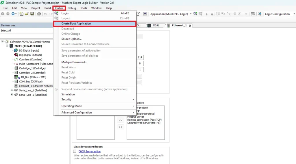
Login to the PLC
Once the project has been built successfully, establish communication with the controller
There are two ways to go online:
- Select Online > Login
- Click the Login button (green arrows) on the toolbar.
Machine Expert compares the project on the computer with the application currently stored in the PLC
If the PLC does not already contain the same application, the software will automatically prepare to download the new project.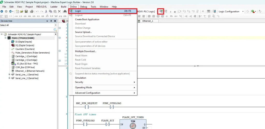
Confirm the Download Warning
If the controller contains a different application, a warning dialog appears stating:
WARNING – UNINTENDED EQUIPMENT OPERATION
This message reminds you that downloading a new application will overwrite the existing PLC program.
Before continuing:
- Verify you are connected to the correct PLC.
- Confirm the controller IP address.
- Confirm the project is intended for that controller.
If everything is correct, proceed with the download. Schneider displays this warning whenever an application on the controller will be replaced.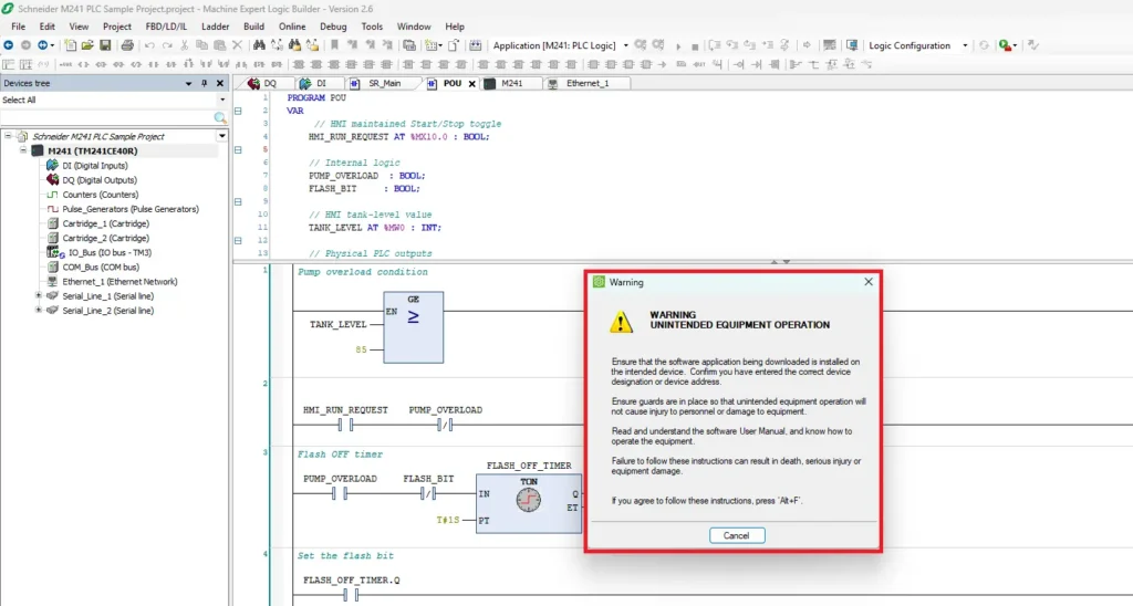
Enter the PLC User Credentials
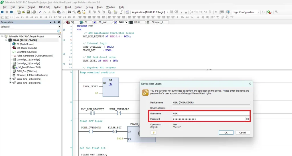
If user access protection is enabled, the Device User Logon window appears.
Enter the PLC credentials:
User name
Password
Then select OK
After successful authentication, Machine Expert downloads the application to the controller. If security is disabled on the controller, this dialog does not appear.
Acknowledge the Post Configuration Warning
After the download completes, a Post Configuration Warning may appear indicating that a post configuration is active on the controller.
Review the message and select OK to continue.
This notification simply informs you that additional controller configuration settings are present. It does not prevent the application from running.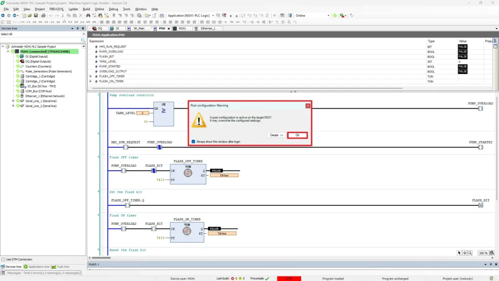
Place the Controller into RUN Mode
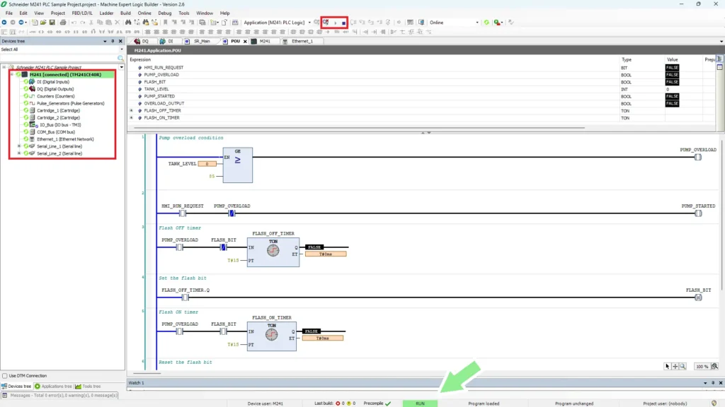
If the PLC is in STOP mode after downloading, start the controller by clicking the Run button on the toolbar.
Alternatively:
Online > Operating Mode > Run
Once the PLC begins executing the application:
- The status bar changes from STOP to RUN.
- The RUN indicator turns green.
- The ladder logic executes continuously.
- Inputs, outputs, and timers update in real time.
A green RUN status confirms that the controller is actively scanning the program.
Then verify the program operation. With the controller running, verify that the ladder logic operates as expected.
HMI Configuration and Project Build
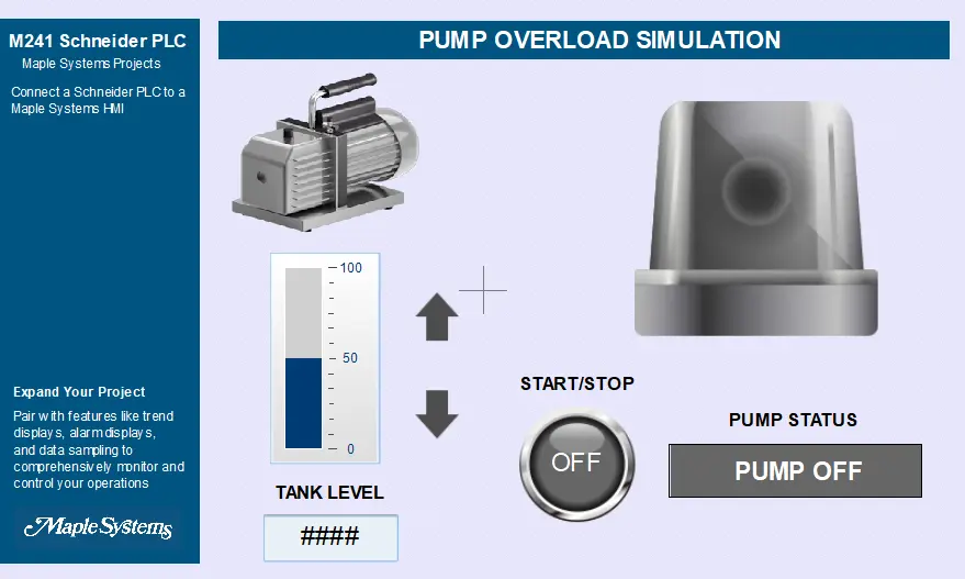
This section explains how to create an EBPro project, configure communication with the Schneider Electric M241 PLC using Schneider Modbus TCP/IP, and build the HMI application used for a pump overload simulation.
Creating the HMI Project in EBPro
The following steps show how to create a new EBPro project, configure communication with a Schneider M241 PLC using Schneider Modbus TCP/IP, and build the HMI application shown in the following examples.
Instructions: Creating the HMI Project in EBPro
Create a New EBPro Project
Launch EBPro and create a new project.
In the New Project window:
- Expand the cMT X Series
- Select cMT2078X / cMT2078X (V2)
- Click OK
EBPro creates a new project using the native 800 × 480 resolution of the cMT2078XV2 HMI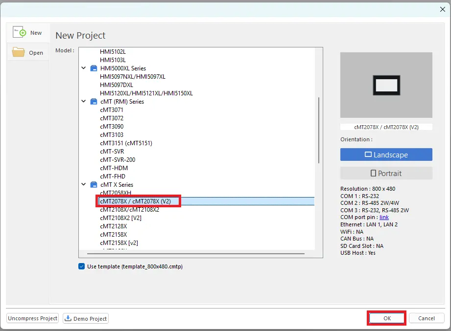
Configure Communication with the Schneider PLC
Before creating any HMI objects, configure communication with the PLC.
Select:
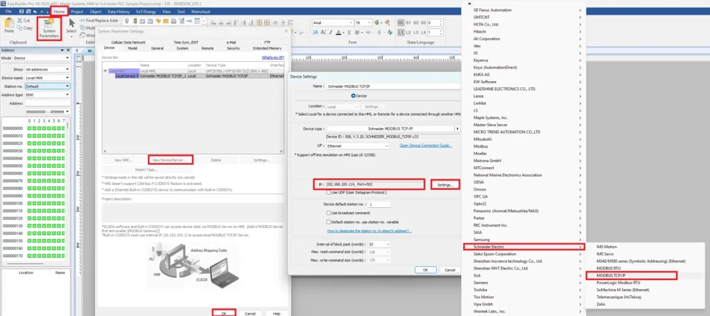
Home > System Parameters
The System Parameter Settings window opens.
- Add the PLC Driver
- Select New Device/Server
- Expand Schneider Electric
- Select MODBUS TCP/IP
- Click OK
The Device Settings window opens
Configure the communication settings:
Schneider MODBUS TCP/IP
Ethernet
192.168.100.114
502
The default Modbus TCP port is 502, which is supported by the Schneider M241 Modbus Server.
Select Settings if additional Ethernet options need to be modified.
When finished:
Select OK
Verify the Schneider device appears in the device list.
Select OK again to save the System Parameters.
The HMI is now configured to communicate with the PLC over Ethernet using Schneider Modbus TCP/IP.
Add the Start/Stop Toggle Switch
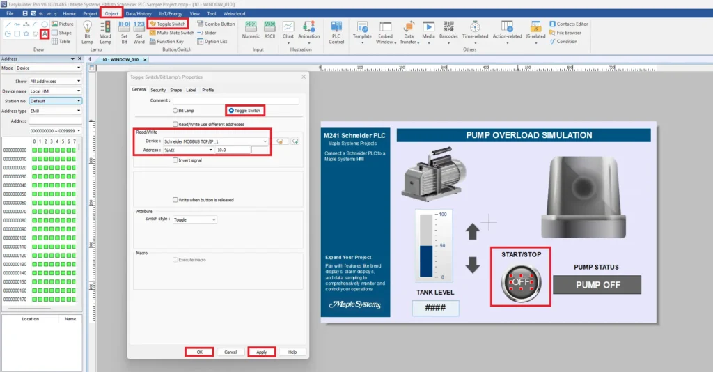
The Start/Stop button allows the operator to write a maintained run command to the PLC.
Select:
Object > Toggle Switch
Place the switch on the HMI screen.
Open the Toggle Switch properties.
Configure the following:
Device: Schneider MODBUS TCP/IP_1
Address Type: %MX
Address: 10.0
The %MX10.0 memory bit matches the PLC variable:
HMI_RUN_REQUEST AT %MX10.0 : BOOL;
Each time the operator presses the button, the HMI toggles the PLC memory bit ON or OFF.
Add the Pump Status Indicator
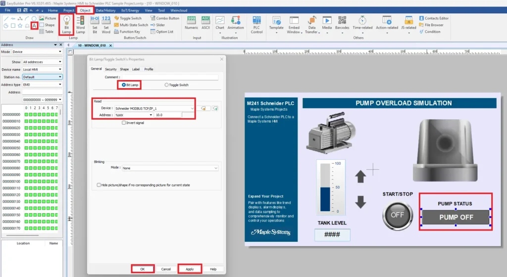
Next, create an indicator that displays whether the pump is running.
Select:
Object > Bit Lamp
Put the Bit Lamp beside the Start/Stop button.
Configure:
Device: Schneider MODBUS TCP/IP_1
Address Type: %MX
Address: 10.0
The Bit Lamp continuously reads %MX10.0.
When the bit is ON, the lamp indicates the pump run request is active.
When the bit is OFF, the lamp indicates the pump is stopped.
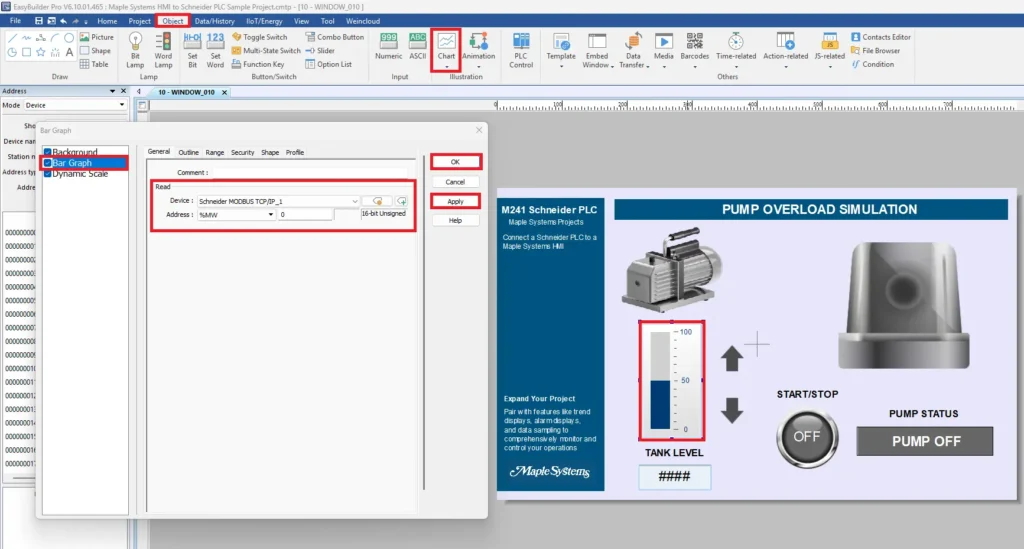
Add the Tank Level Bar Graph
The bar graph displays the current tank level received from the PLC.
Select:
Object > Chart > Bar Graph
Insert a Bar Graph.
Open the Bar Graph properties.
Configure the Read Address
Configure:
Device: Schneider MODBUS TCP/IP_1
Address Type: %MW
Address: 0
Data Type: 16-bit Unsigned
The HMI now reads the PLC word:
TANK_LEVEL AT %MW0 : INT;
Configure the Measurement Range
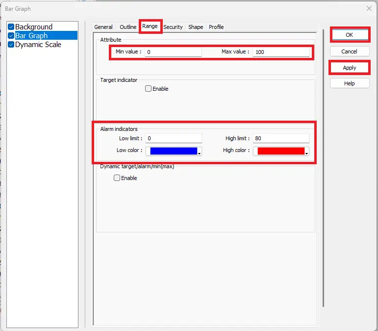
Open the Range tab.
Configure:
Minimum 0
Maximum 100
These values match the simulated tank level.
Configure the alarm colors:
Low Limit 0
High Limit 80
Low Color Blue
High Color Red
When the tank level exceeds 85, the upper portion of the bar graph changes to red, providing a visual indication that the tank is approaching the overload threshold.
Add the Tank Level Numeric Display
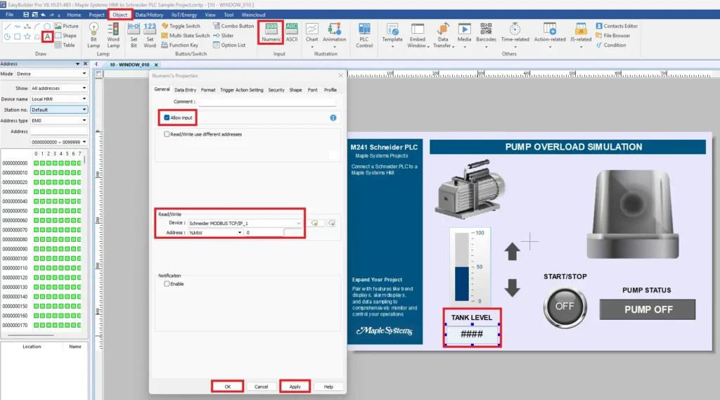
To display the exact tank level value, insert a Numeric Display.
Select:
Object > Numeric
Place the numeric object below the bar graph.
Configure:
Allow Input: Enabled
Device:: Schneider MODBUS TCP/IP_1
Address Type:: %MW
Address: 0
The numeric display continuously reads %MW0 and displays the current tank level value.
Because Allow Input is enabled, the operator can also type a value directly into the HMI to update the PLC memory word.
Add Tank Level Increase and Decrease Buttons
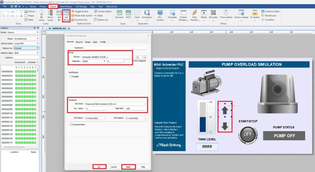
To simulate changing tank levels, configure two Set Word buttons.
Select:
Object > Set Word
Create an Increase button.
Configure:
Device: Schneider MODBUS TCP/IP_1
Address Type: %MW
Address: 0
Configure the button attributes:
Set Style: Press and Hold Increment (JOG++)
Increment Value: 5
High Limit: 100
Repeat the process for the decrease button using Press and Hold Decrement (JOG–).
These buttons allow the operator to increase or decrease the simulated tank level in 5-unit increments directly from the HMI.
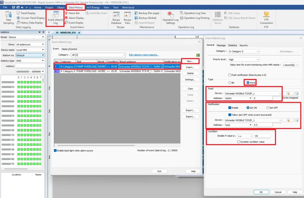
Configure the Pump Overload Alarm
The HMI alarm activates when the tank level reaches the overload threshold.
Select:
Data/History > Event (Alarm) Log
Create a new alarm by selecting New
Configure the alarm:
Under General
Category: Category 0
Priority: High
Type: Word
Device: Schneider MODBUS TCP/IP_1
Address %MW0
Notification
Configure the notification output:
Enable: Checked
Notification Mode: Set ON
Device: Schneider MODBUS TCP/IP_1
Address: %QX0.5
Configure the alarm condition:
Condition: Greater Than or Equal To
Value: 85
When %MW0 reaches 85, the alarm becomes active and sets output %QX0.5.
Configure the Alarm Recovery
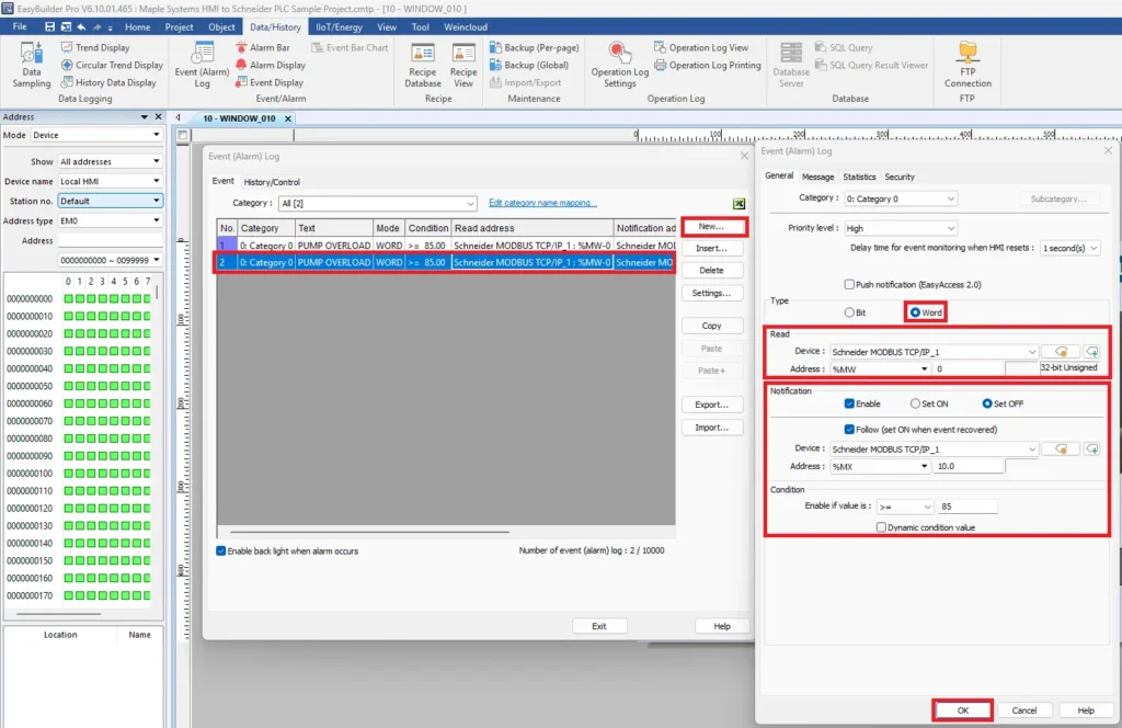
Create a second alarm to reset the output after the overload clears.
Select New again
Configure the same read address:
Device: Schneider MODBUS TCP/IP_1
Address: %MW0
Configure the notification:
Notification Mode: Set OFF
Device: Schneider MODBUS TCP/IP_1
Address: %MX10.0
Configure the condition:
Condition: Greater Than or Equal To
Value: 85
With Follow enabled, the notification automatically resets when the alarm condition clears, returning the HMI to its normal operating state.
Add the Pump Overload Alarm Indicator
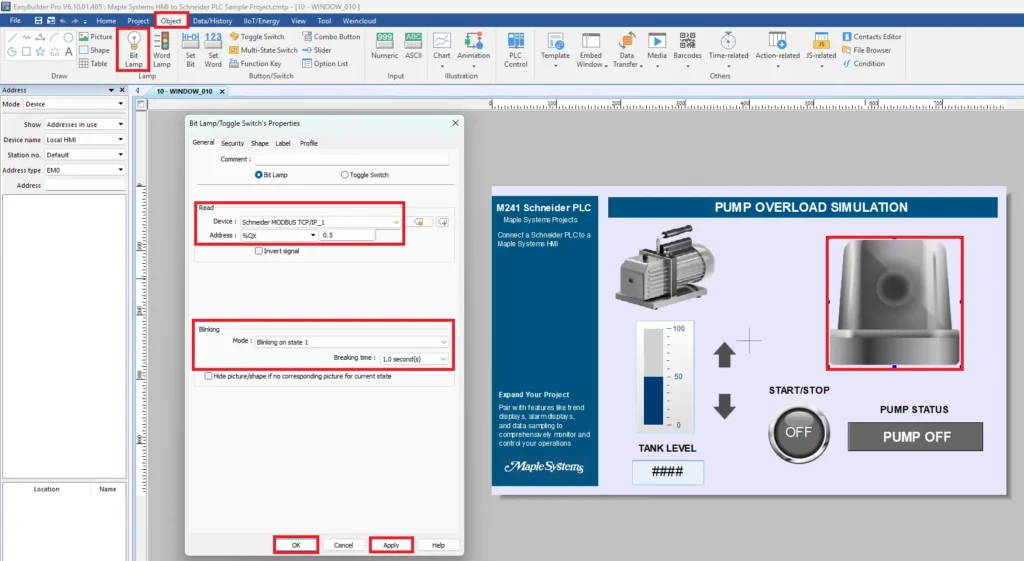
To provide a visual indication of an overload condition, add a second Bit Lamp that monitors the PLC output controlling the alarm.
Select:
Object > Bit Lamp
Place the Bit Lamp over the alarm beacon image.
Open the Bit Lamp Properties window and configure the following settings:
Mode: Bit Lamp
Device: Schneider MODBUS TCP/IP_1
Address Type: %QX
Address: 0.5
The %QX0.5 output is energized by the PLC whenever the tank level reaches the overload threshold. When the output turns ON, the Bit Lamp illuminates to indicate an active pump overload alarm.
Configure the Blinking Effect
To make the alarm more noticeable, enable the built-in blinking animation.
Under the Blinking section, configure:
Mode: Blinking on state 1
Breaking Time: 1.0 second
This causes the alarm beacon to flash once per second whenever %QX0.5 is ON, providing a clear visual indication that the pump overload condition is active.
Configure the Alarm Label
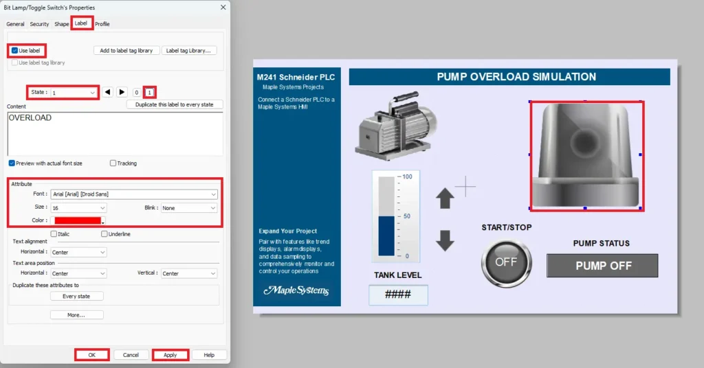
To clearly identify the alarm state, configure a text label that appears when the alarm beacon is active.
Open the Label tab in the Bit Lamp Properties window.
Enable Use label, then configure the following settings:
State: 1
Label: OVERLOAD
Font: Arial
Font Size 16
Font Color Red
The label is assigned to State 1, meaning the text OVERLOAD is displayed only when the Bit Lamp is ON. Using a bold red font makes the active alarm condition easy to identify from a distance.
With the blinking animation and label enabled, the alarm beacon flashes and displays OVERLOAD whenever PLC output %QX0.5 is energized, providing operators with an immediate visual indication that a pump overload condition has occurred.
Downloading to the HMI
After configuring the HMI objects and communication settings, the final step is to download the project to the Maple Systems HMI and verify communication with the Schneider Electric M241 PLC.
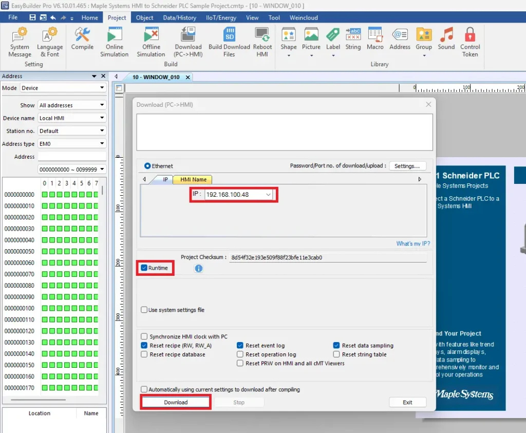
Download the Project to the Maple Systems HMI
After configuring the HMI objects and communication settings, download the project to the Maple Systems HMI to begin testing with the Schneider M241 PLC.
Instructions: Download the Project to the Maple Systems HMI
Downloading the Project to the HMI
Download the Project
- Select Project > Download (PC → HMI)
- The Download (PC → HMI) window opens.
Configure the download settings:
Download Method: Ethernet
HMI IP Address: 192.168.100.48
Runtime: Enabled
Verify that the HMI IP address matches the address configured on your cMT2078XV2.
Once the connection settings are confirmed, select Download.
EBPro compiles the runtime project and transfers it to the HMI over Ethernet. Depending on the project size and network speed, the download typically completes within a few seconds.
Launch the Runtime and Verify the HMI Operation
After the download finishes, the HMI automatically starts the runtime application.
If Runtime was enabled during the download, no additional configuration is required. The project immediately begins communicating with the Schneider M241 PLC using the Schneider Modbus TCP/IP driver.
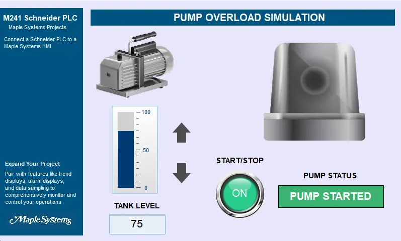
Once the runtime is active, verify that the HMI communicates correctly with the PLC.
With the tank level below the overload threshold, the HMI should display:
- Tank level value updating from %MW0
- Blue tank level bar graph
- Green START/STOP button when the run request is active
- PUMP STARTED status indicator
- Alarm beacon OFF
This confirms that the HMI is successfully reading data from the PLC and displaying the current process status.
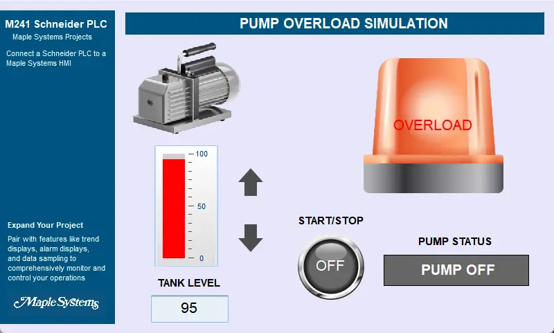
Simulate a Pump Overload
Increase the tank level using the on-screen increase button until the value reaches or exceeds 85.
When the overload condition occurs, the HMI automatically updates to display:
- Tank level increasing above the alarm threshold
- Bar graph changing from blue to red
- Alarm beacon flashing
- OVERLOAD label displayed on the beacon
- PUMP OFF status displayed
- Start/Stop button returning to the OFF state
These changes confirm that the PLC logic and HMI are communicating correctly. The PLC detects the overload condition, turns off the pump, energizes the alarm output, and the HMI immediately reflects the new operating state.
| HMI Object | PLC Address | Expected Operation |
|---|---|---|
| Start/Stop Toggle | %MX10.0 | Starts and stops the pump |
| Pump Status Indicator | %QX0.4 | Displays PUMP STARTED when the pump is running |
| Pump Overload Beacon | %QX0.5 | Flashes and displays OVERLOAD during an alarm |
| Tank Level Bar Graph | %MW0 | Displays the current tank level |
| Tank Level Numeric Display | %MW0 | Displays the current tank level value |
| Increase/Decrease Buttons | %MW0 | Adjust the simulated tank level |
| Alarm Log | %MW0 | Records pump overload events |
Live Simulation
This section demonstrates communication between a Maple Systems cMT2078Xv2 HMI and a Schneider Electric Modicon M241 (TM241CE40R) PLC using Schneider Modbus TCP/IP.
The live simulation uses cMT Viewer to remotely monitor the HMI and control the PLC over Ethernet, allowing the operator to start and stop the pump while viewing real-time system status.
It simulates a pump overload condition. When the tank level reaches the overload threshold, the PLC immediately stops the pump, activates the alarm output, and updates the HMI. The HMI displays the flashing overload beacon, changes the pump status, and updates the tank level and alarm information in real time.
This simulation demonstrates how a Maple Systems HMI and Schneider Electric M241 PLC work together to provide reliable monitoring, operator control, and alarm indication for industrial automation applications using Schneider Modbus TCP/IP.
You are now ready to apply your Maple Systems HMI and Schneider PLC in real-world applications. By combining the functionality of the Schneider PLC with the visualization and interface capabilities of the Maple Systems HMI, you are prepared to design practical automation solutions and implement them in real operating environments.
Recap
Connecting a Maple Systems HMI to a Schneider Electric Modicon M241 PLC is a straightforward process using the Schneider Modbus TCP/IP driver available in EBPro. In this article, you learned how to configure Ethernet communication between the HMI and PLC, create a new Machine Expert Logic Builder project, build a ladder logic program for a pump overload simulation, and download the application to the M241 controller.
You also created an HMI project in EBPro by adding a Start/Stop toggle switch, pump status indicator, tank level controls, bar graph, overload alarm, and event logging to provide a complete operator interface. Finally, you downloaded the project to the Maple Systems HMI and verified live communication using cMT Viewer, demonstrating real-time monitoring and control of the Schneider PLC over Modbus TCP/IP.
Next Steps
Now that communication between the Maple Systems HMI and Schneider M241 PLC is established, you can expand this project to more closely resemble a real industrial application. Add additional I/O such as level switches, pressure sensors, flow meters, and motor feedback to monitor more complex processes.
You can also incorporate alarm history, trend displays, recipes, data sampling, user security, and remote monitoring to enhance operator visibility and system functionality. These same communication and development principles can be applied to a wide range of automation applications, including water and wastewater treatment, pumping stations, manufacturing equipment, packaging systems, and material handling solutions.
Sample Project
This integration tutorial uses the Connect a Schneider PLC to a Maple Systems HMI sample project.
Resources & Documentation
The following guides and documentation are specific to the hardware used in this integration tutorial and will help you with setup, configuration, and programming:
Looking for additional learning resources? Explore our library of tutorials, example projects, and software tools to help you get the most out of your system:
Also, browse our Support Center for a complete list of installation guides, FAQs, and additional technical documentation.

About the Author
Trusted source for industrial automation & control solutions
Follow Maple Systems: