
Introduction
All Maple Systems HMIs programmed with EBPro (EasyBuilder Pro), including every cMT X Series and cMT Series model, are compatible with Modbus Server (COM/Ethernet). Configure your Controller and HMI/cMT with the following parameters to establish reliable communication.
HMI Setting
| Parameters | Recommended | Options | Notes |
|---|---|---|---|
| PLC type | MODBUS Server (COM/Ethernet) | ||
| PLC I/F | RS232 | RS232, RS485, Ethernet | Ethernet supports UDP or TCP/IP protocol |
| Baud rate | 9600 | 9600~115200 | |
| Data bits | 8 | 8 | |
| Parity | Even | Even, Odd | |
| Stop bits | 1 | 1 | |
| PLC sta. no. | 1 | 1-31 | HMI Modbus Station No. |
| Port no. | 502 | ||
| Online simulator | YES | ||
| Extend address mode | NO | ||
| Broadcast command | NO |
NOTE: If HMI is Modbus Server, connecting two or more Modbus Servers with one Modbus RTU via RS485 4W is not supported. To do so, use RS485 2W instead.
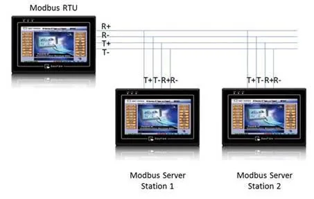
PLC Setting
| Communication mode | Value |
|---|---|
| Communication mode | Modbus RTU protocol |
Modbus Server UDP Protocol Setting
MODBUS Server (Ethernet) supports UDP communication protocol. To use UDP mode, go to System Parameter Settings in editing software, in Device list click New, for PLC type select Modbus Server, set PLC I/F to Ethernet, and select Use UDP (User Datagram Protocol) to finish setting.
Modbus Server Port No. can be changed by clicking Settings.
Modbus Server Port No. cannot be set identically to HMI Port No. When doing so, the warning message below will be shown requesting users to change setting.
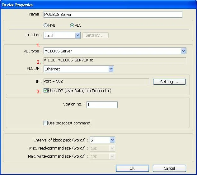
NOTE: A maximum of 64 Clients can be connected simultaneously. Modbus Server Port No. cannot be identical to HMI Port No.
Modbus Server TCP/IP Protocol Setting
MODBUS Server (Ethernet) supports TCP/IP communication protocol. Go to System Parameter Settings in editing software, in Device list click New, for PLC type select Modbus Server, set PLC I/F to Ethernet to finish setting.
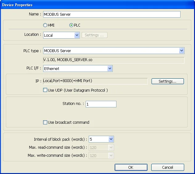
For Modbus Server TCP/IP, HMI Port No. is the same as Modbus Server Port No. To change Port No. go to System Parameter Settings / Model, the default Port No. is 8000, and it is allowed to change Modbus Server Port No. here.
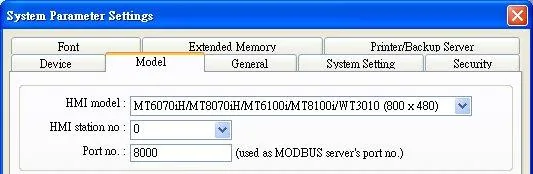
MODBUS TCP/IP Gateway
By adding MODBUS Server with Ethernet interface, the MODBUS TCP/IP Gateway feature can be enabled by selecting the Enable check box.
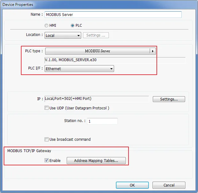
Note the following two points when enabling the MODBUS TCP/IP Gateway:
- The original mapping between the MODBUS Server and the HMI address will be canceled.
- The SCADA cannot read from or write to the addresses defined in different Address Mapping Tables at one time.
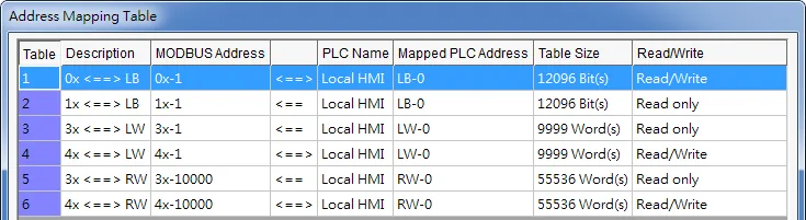
NOTE: The following functions are only supported by cMT series models.

Device Address
| Bit/Word | Device type | Format | Range | Memo |
|---|---|---|---|---|
| B | LB | dddd | 0 ~ 9998 | Mapping to 0x/1x 1 ~ 9999 |
| W | LW | dddd | 0 ~ 9998 | Mapping to 3x/4x 1 ~ 9999 |
| W | RW | ddddd | 0 ~ 55536 | Mapping to 3x/4x 10000 ~ 65536 |
LB0 = 0x0001, LB1 = 0x0002, LW0 = 3x0001, LW1 = 3x0002
Supported Modbus Server Function Codes
| Function Code | Description |
|---|---|
0x01 | Read Coils |
0x02 | Read Discrete Inputs |
0x03 | Read Holding Register |
0x04 | Read Input Register |
0x05 | Write Single Coil |
0x06 | Write Single Register |
0x0f | Write Multiple Coils |
0x10 | Write Multiple Registers |
Modbus Server Error Codes
| Error Code | Definition | Condition |
|---|---|---|
| 01 | Incorrect function code | The function code is not supported. |
| 02 | Incorrect read address | The read address is not within the range. |
| 03 | Incorrect data | The data read is incorrect, for example, the data length is 0. |
| 251 | Incorrect data | Read/Write exceeding number of words from/to the register of the Modbus device. |
| 252 | Incorrect data | Modbus device replies incorrect data format. |
| 253 | Incorrect data | Modbus device checksum error. |
Wiring Diagrams
NOTE: The serial port pin assignments may vary between HMI models.
Diagram 1: RS-232
| HMI | Direction | PLC |
|---|---|---|
| Pin assignments | RS232 | |
| Rx | ↔ (bidirectional) | TXD |
| Tx | ↔ (bidirectional) | RXD |
| GND | ↔ (bidirectional) | GND |
| ↕︎ (tie) | RTS CTS |
Diagram 2: RS-485 4W
| HMI | Direction | PLC |
|---|---|---|
| Pin assignments | RS485 4W | |
| Rx- | ↔ (bidirectional) | Tx- |
| RX+ | ↔ (bidirectional) | Tx+ |
| Tx- | ↔ (bidirectional) | Rx- |
| Tx+ | ↔ (bidirectional) | Rx+ |
| GND | ↔ (bidirectional) | GND |
Diagram 3: RS-485 2W
| HMI | Direction | PLC |
|---|---|---|
| Pin assignments | RS485 2W | |
| Data- | ↔ (bidirectional) | D- |
| Data+ | ↔ (bidirectional) | D+ |
| GND | ↔ (bidirectional) | GND |
NOTE: Setting more than one Modbus Server in HMI Device List is of no effect.
Diagram 4: Ethernet Cable
