
Introduction
All Maple Systems HMIs programmed with EBPro (EasyBuilder Pro), including every cMT X Series and cMT Series model, are compatible with a Mitsubishi MR-J3/J4-A. Configure your Controller and HMI/cMT with the following parameters to establish reliable communication.
HMI Settings
| Parameters | Recommended | Options | Notes |
|---|---|---|---|
| PLC type | Mitsubishi MR J3/J4 A | ||
| PLC I/F | RS485 4W | RS232/RS485 | |
| Baud rate | 9600 | 9600~115200 | |
| Parity | Even | ||
| Data bits | 8 | ||
| Stop bits | 1 | ||
| PLC sta. no. | 0 | 0~31 |
Device Address
| Bit/Word | Device | Format | Range | Memo |
|---|---|---|---|---|
| B | EIP | DD | 0 ~ 31 | External input pin status read 3 |
| B | EOP | DD | 0 ~ 31 | External output pin status read 3 |
| B | SP | D | 0 ~ 6 | |
| W | PA | DDDD | 1 ~ 1032 | Basic Setting 4 |
| W | PB | DDDD | 1 ~ 1064 | Gain / Filter Setting 4 |
| W | PC | DDDD | 1 ~ 1080 | Extension Setting 4 |
| W | PD | DDDD | 1 ~ 1048 | Input / Output Setting 4 |
| W | Status | DD | 0 ~ 57 | Amplifier Status 1 |
| W | Alarm | D | 0 ~ 6 | Alarm |
| W | Alarm_T | D | 0 ~ 6 | Alarm Time (Hour) 2 |
| W | Mode | D | 1 ~ 4 | Write Only, Mode Setting 2 |
| W | Speed | D | 0 ~ 1 | Write Only, Set Current Speed 2 |
| W | Acc | D | 0 ~ 1 | Write Only, Set Acceleration 2 |
| W | Rotation | D | 0 ~ 1 | Write Only, Rotation Direction 2 |
| W | End | D | 0 ~ 1 | Write Only, End 2 |
| W | M_dist | D | 0 ~ 1 | Write Only, Moving Distance 2 |
| W | Rot_P | D | 0 ~ 1 | Write Only, Rotation Position 2 |
| W | P_start | D | 0 ~ 1 | Write Only, Start Positioning 2 |
| W | Cur_Alarm | D | 0 ~ 1 | Current Alarm |
| W | PE | DDDD | 1 ~ 1064 | Extension Setting 2 4 |
| W | PF | DDDD | 1 ~ 1048 | Extension Setting 3 4 |
| W | PO | DDDD | 1 ~ 1048 | Extension Setting 2 4 |
| W | PS | DDDD | 1 ~ 1048 | Extension Setting 3 4 |
| W | PL | DDDD | 1 ~ 1048 | Extension Setting 2 4 |
| W | PT | DDDD | 1 ~ 1048 | Extension Setting 3 4 |
| DW | POS | DDDD | 1 ~ 1255 | |
| DW | SPD | DDDD | 1 ~ 1255 | |
| DW | ACT | DDDD | 1 ~ 1255 | |
| DW | DCT | DDDD | 1 ~ 1255 | |
| DW | DWL | DDDD | 1 ~ 1255 | |
| DW | AUX | DDDD | 1 ~ 1255 | |
| DW | MCD | DDDD | 1 ~ 1255 |
Note 1: Status Register Address Map
| Address | Item |
|---|---|
| 0 | Cumulative feedback pulses |
| 1 | Servo motor speed |
| 2 | Droop pulse |
| 3 | Cumulative cmd. Pulses |
| 4 | Command pulse frequency |
| 5 | Analog speed command voltage |
| 6 | Analog torque command voltage |
| 7 | Regenerative load ratio |
| 8 | Effective load ratio |
| 9 | Peak load ratio |
| 10 | Instantaneous torque |
| 11 | Within one-revolution position |
| 12 | ABS counter |
| 13 | Load inertia moment ratio |
| 14 | Bus voltage |
| 15 | Load-side cumulative feedback pulses |
| 16 | Load-side droop pulses |
| 17 | Load-side encoder information 1 |
| 18 | Load-side encoder information 2 |
| 22 | Motor thermistor temperature |
| 23 | Motor-side cumulative feedback pulses (before gear) |
| 24 | Electrical angle |
| 30 | Motor-side / load-side position deviation |
| 31 | Motor-side / load-side speed deviation |
| 32 | Encoder inside temperature |
| 33 | Setting time |
| 34 | Oscillation detection frequency |
| 35 | Number of tough drive operations |
| 40 | Unit power consumption |
| 41 | Unit total power consumption |
NOTE: 2 These are write-only registers. Their usage is to run Jog Mode and Positioning Mode.
NOTE: 3 These are read-only registers.
NOTE: 4 Data written to address 1–XX is written to RAM. Data written to address 1001–10XX is written to ROM.
EIP: External Input Pin Status
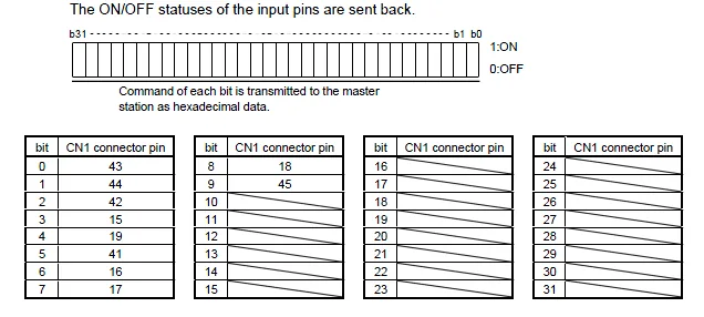
The ON/OFF statuses of the input pins are sent back. Command of each bit is transmitted to the master station as hexadecimal data (1: ON, 0: OFF). Bits b31–b0 map to CN1 connector pins as follows:
EOP: External Output Pin Status
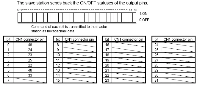
The slave station sends back the ON/OFF statuses of the output pins. Command of each bit is transmitted to the master station as hexadecimal data (1: ON, 0: OFF). Bits b31–b0 map to CN1 connector pins as follows:
The Status register provides amplifier status information. The address values correspond to the following items:
Jog Mode and Positioning Mode
The following instructions describe how to use EBPro (EasyBuilder8000 / EasyBuilderPro) to run Jog Mode and Positioning Mode with the Mitsubishi MR-J3/J4-A servo amplifier.
Jog Mode
To run Jog Mode, follow the steps listed sequentially:
- Set Jog Mode
- Set rotation speed
- Set acceleration
- Set forward / reverse rotation direction
- End
In the EBPro (EasyBuilder8000 / EasyBuilderPro) editing window, set the write address of Speed to Local HMI LW0 (the address can be user-defined) and set Acc (Acceleration) to LW1.
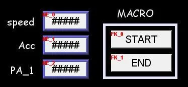
NOTE: To run Jog Mode, communication with the device must be continuous, allowing an interval of less than 0.5 seconds. If the interval exceeds 0.5 seconds, the motor will be locked. In this example, only one register PA_1 is set to read the device value.
Start Macro
macro_command main()
short speed
short acc
short mode
mode = 1  // This represents Jog Mode.
SetData(mode, "MITSUBISHI MR J3 A", Mode, 1, 1)  // Set driver mode to Jog.
GetData(speed, "Local HMI", LW, 0, 1)  // Save LW0 value to speed.
SetData(speed, "MITSUBISHI MR J3 A", Speed, 0, 1) // Set motor operating speed.
GetData(acc, "Local HMI", LW, 1, 1)
SetData(acc, "MITSUBISHI MR J3 A", Acc, 0, 1) // Set motor acceleration.
short motion
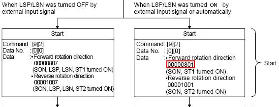
motion = 0x0801  // Special code, see Note 1.
SetData(motion, "MITSUBISHI MR J3 A", Rotation, 0, 1) // Rotate.
end macro_commandCode language: JavaScript (javascript)
NOTE: Note 1 — Original Factory Manual:
End Macro
macro_command main()
short stop
stop = 1  // See Note 2.
SetData(stop, "MITSUBISHI MR J3 A", End, 1, 1)
end macro_commandCode language: JavaScript (javascript)
NOTE: Note 2 — Original Factory Manual:

Positioning Mode
In the EBPro (EasyBuilder8000 / EasyBuilderPro) editing window, set the write address of Speed to Local HMI LW2 (the address can be user-defined), set Acc (Acceleration) to LW3, and set Move distance to LW4 (DW format).
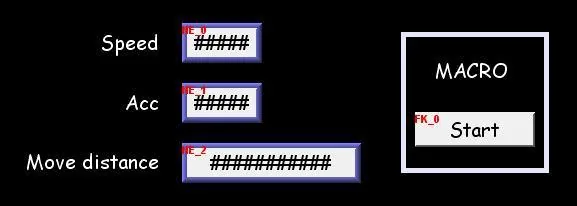
Positioning Macro
macro_command main()
short mode
mode = 0x2  // Positioning Mode
SetData(mode, "MITSUBISHI MR J3 A", Mode, 1, 1)
short speed
GetData(speed, "Local HMI", LW, 2, 1)
SetData(speed, "MITSUBISHI MR J3 A", Speed, 0, 1)
short acc
GetData(acc, "Local HMI", LW, 3, 1)
SetData(acc, "MITSUBISHI MR J3 A", Acc, 0, 1)
short dist
GetData(dist, "Local HMI", LW, 4, 1)
SetData(dist, "MITSUBISHI MR J3 A", M_dist, 0, 1)
short rot_P
rot_P = 1        // Set to 0: Forward Rotation  1: Reverse Rotation
SetData(rot_P, "MITSUBISHI MR J3 A", Rot_P, 0, 1)
short rotat
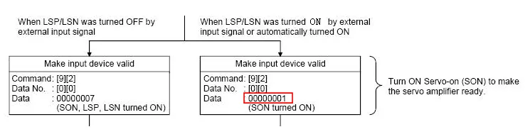
rotat = 1   // See Note 3.
SetData(rotat, "MITSUBISHI MR J3 A", Rotation, 0, 1)
SetData(rot_P, "MITSUBISHI MR J3 A", P_start, 0, 1) // Start Positioning.
end macro_commandCode language: JavaScript (javascript)
NOTE: Note 3 — Original Factory Manual:
Wiring Diagram
NOTE: The serial port pin assignments may vary between HMI models.
RS-485 4W
| HMI | Direction | PLC |
|---|---|---|
| Pin assignments | CN3 RS485 4W RJ45 Male | |
| Rx- | ↔ (bidirectional) | 4 |
| RX+ | ↔ (bidirectional) | 5 |
| Tx- | ↔ (bidirectional) | 6 |
| Tx+ | ↔ (bidirectional) | 3 |
| GND | ↔ (bidirectional) | 7 |