
Introduction
All Maple Systems HMIs programmed with EBPro (EasyBuilder Pro), including every cMT X Series and cMT Series model, are compatible with a Mitsubishi FX5U. Configure your Controller and HMI/cMT with the following parameters to establish reliable communication.
Supported Series: Mitsubishi FX5U/FX5UC
Website: http://www.mitsubishi-automation.com
HMI Settings
| Parameters | Recommended | Options | Notes |
|---|---|---|---|
| PLC type | Mitsubishi FX5U | ||
| PLC I/F | RS485 4w | ||
| Baud rate | 19200 | 9600 ~ 115200 | |
| Data bits | 8 | 7, 8 | |
| Parity | None | None/Odd/Even | |
| Stop bits | 1 | 1, 2 | |
| PLC sta. no. | 0 | 0 ~ 15 | |
| Message pattern | 1 | 1, 4, 5 | Message Pattern *Note1 |
| Network number | 0 | 0 ~ 999 | |
| Online simulator | YES | ||
| Extend address mode | NO |
NOTE: *Note1 — Message Pattern options:
Pattern 1 (X, Y OCT) = ASCII Mode;
Pattern 4 (X, Y OCT) = ASCII Mode (CR, LF);
Pattern 5 = Binary Mode.
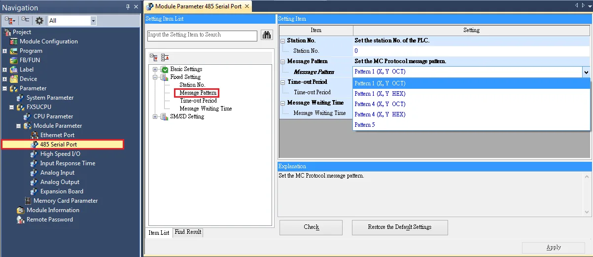
PLC Settings
| Setting | Value |
|---|---|
| Communication Protocol | MC Protocol |
| Sum Check Code | Added |
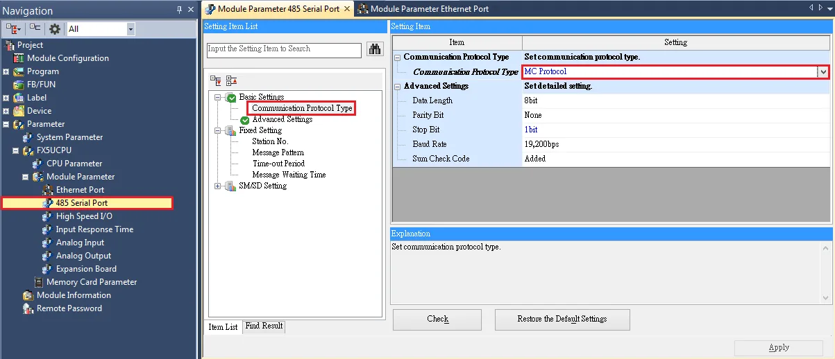
Import Tags
GX Works3 Export Tags
Open Global Label context menu
In GX Works3, navigate to Project → Label → Global Label → Global, then right-click and select Export to File.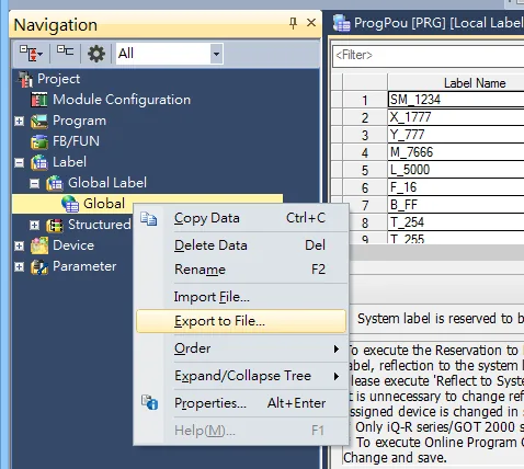
Export to XML File
In the Export to File dialog, select Export to XML File (includes assignment device of structures and structure arrays), then click Execute.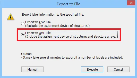
EBPro (EasyBuilder Pro) Import Tags
Open Import Tags
After configuring System Parameters and creating the driver, click Import Tags.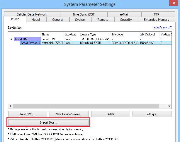
Select XML file and tags
Select the.XMLfile exported from GX Works3, then choose the tags you want to import.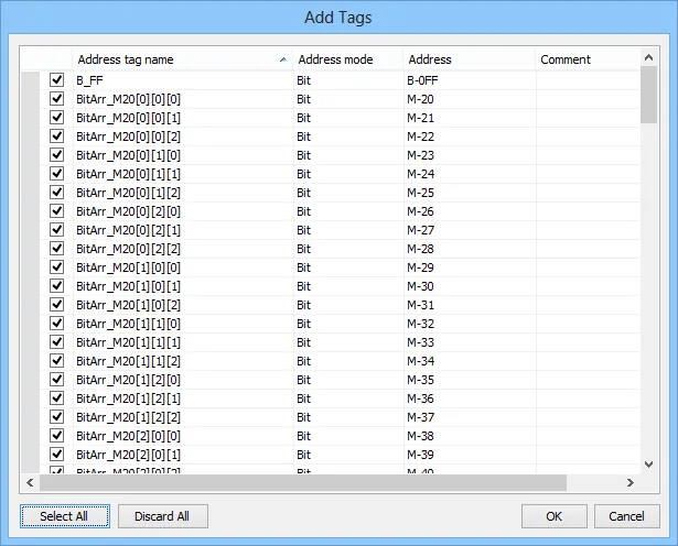
Confirm successful import
A confirmation dialog will appear indicating that tag information has been imported successfully. Click OK.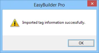
Limitations
- Structure in structure and array in structure are not supported.
- If
TN,CN,LCN,SN, and other addresses are used in the structure, three members of Contact, Coil, and Current Value will be automatically generated. - The String type will end with
0x00. If the length is set to 16 words, then a complete string will be 17 words in length.
Support Data Type List
| Data Type | Support |
|---|---|
| Bit | ✓ |
| Word [Unsigned] / Bit String [16-bit] | ✓ |
| Double Word [Unsigned] / Bit String [32-bit] | ✓ |
| Word [Signed] | ✓ |
| Double Word [Signed] | ✓ |
| FLOAT [Single Precision] | ✓ |
| Time | ✓ |
| String(32) | ✓ |
| Pointer | ✗ |
| Timer | ✓ |
| Counter | ✓ |
| Long Counter | ✓ |
| Retentive Timer | ✓ |
Device Address
| Bit/Word | Device | Format | Range | Memo |
|---|---|---|---|---|
| B | LCS | DDDD | 0 ~ 1023 | Long counter Contact *Note1 |
| B | LCC | DDDD | 0 ~ 1023 | Long counter Coil *Note1 |
| B | SM | DDDD | 0 ~ 9999 | Special Relay |
| B | X | OOOO | 0 ~ 1777 | Input Relay |
| B | Y | OOOO | 0 ~ 1777 | Output Relay |
| B | M | DDDDD | 0 ~ 32767 | Internal Relay |
| B | L | DDDDD | 0 ~ 32767 | Latch Relay |
| B | F | DDDDD | 0 ~ 32767 | Annunciator |
| B | B | HHHH | 0 ~ 7FFF | Link Relay |
| B | TS | DDDD | 0 ~ 1023 | Timer Contact |
| B | TC | DDDD | 0 ~ 1023 | Timer Coil |
| B | SS | DDDD | 0 ~ 1023 | Retentive Timer Contact |
| B | SC | DDDD | 0 ~ 1023 | Retentive Timer Coil |
| B | CS | DDDD | 0 ~ 1023 | Counter Contact |
| B | CC | DDDD | 0 ~ 1023 | Counter Coil |
| B | SB | HHHH | 0 ~ 7FFF | Special Link Relay |
| B | S | DDDD | 0 ~ 4095 | Step relay |
| B | D_Bit | DDDDh | 0 ~ 7999F | Data Register bit |
| B | SD_bit | DDDDDh | 0 ~ 11999F | Special register Bit |
| B | R_bit | DDDDDh | 0 ~ 32767F | File Register Bit |
| B | SW_bit | HHHHh | 0 ~ 7FFFF | Special Link Register Bit |
| B | W_bit | HHHHh | 0 ~ 7FFFF | Link Register Bit |
| DW | LCN | DDDD | 0 ~ 1023 | Long counter Current Value *Note1 |
| DW | LZ | D | 0 ~ 1 | Long Index Register |
| W | SD | DDDDD | 0 ~ 11999 | Special register |
| W | D | DDDD | 0 ~ 7999 | Data Register |
| W | R | DDDDD | 0 ~ 32767 | File Register |
| W | W | HHHH | 0 ~ 7FFF | Link Register |
| W | TN | DDDD | 0 ~ 1023 | Timer Current value |
| W | SN | DDDD | 0 ~ 1023 | Retentive Timer Current value |
| W | CN | DDDD | 0 ~ 1023 | Counter Current value |
| W | SW | HHHH | 0 ~ 7FFF | Special Link Register |
| W | Z | DD | 0 ~ 19 | Index Register |
NOTE: *Note1 — ASCII mode does not support LCS, LCC, or LCN.
Wiring Diagram
NOTE: The serial port pin assignments may vary between HMI models.
RS-485 4W
| HMI | Direction | PLC |
|---|---|---|
| Pin assignments | FX5U RS422 Terminal | |
| Rx- | ↔ (bidirectional) | SDB |
| RX+ | ↔ (bidirectional) | SDA |
| Tx- | ↔ (bidirectional) | RDB |
| Tx+ | ↔ (bidirectional) | RDA |
| GND | ↔ (bidirectional) | SG |