Introduction
All Maple Systems HMIs programmed with EBPro (EasyBuilder Pro), including every cMT X Series and cMT Series model, are compatible with the DNP3 Master (Ethernet) driver. Configure your Controller and HMI/cMT with the following parameters to establish reliable communication.
HMI Settings
| Parameters | Recommended | Options | Notes |
|---|---|---|---|
| PLC type | DNP 3 Master (Ethernet) | ||
| PLC I/F | Ethernet | ||
| Port no. | 20000 | ||
| DNP Source Address | 0 | HMI | |
| DNP Destination Address | 1 | PLC |
Tag Manager
Add Tags
In EBPro (EasyBuilder Pro) navigate to -> [System Parameter Settings] -> [Tag Manager] -> [Add], add a new address tag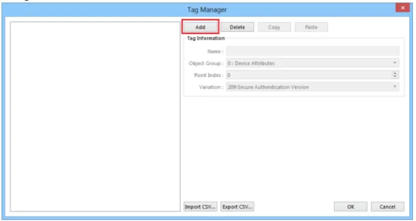
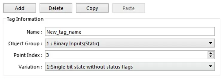
Set tag information
- [Name]: Tag Name, Only ASCII and “_” characters can be used in names.
- [Object Group]: The DNP3 GROUP field supports the following,
- Group 0 : Device Attributes
- Group 1 : Binary Inputs(Static)
- Group 10 : Binary Output(Static)
- Group 20 : Binary Counter(Static)
- Group 30 : Analog Input(Static)
- Group 40 : Analog Output(Status)
- Group 110 : String Group(Static)
- [Point Index]: DNP3 index
- [Variation]: DNP3 Variation
Import / Export CSV
- Convert the created tag information into a CSV file and export it
- This CSV file format is customized. Users can first export the basic address and then edit it to speed up the creation of tag information.
- After editing the csv file, use the import csv function to import it.

Special tag address usage
To write a Binary output object, you need to use multiple tag addresses to work together. First set the following parameters (steps 1-4), and then use (step 5) parameters to send it out.
Set: Control Code : USINT parameter
- 0x01 : Pulse On
- 0x02 : Pulse Off
- 0x03 : Latch On
- 0x04 : Latch Off
Set: OnTime : UINT parameter
– Pulse On durationSet: OffTime : UINT parameter
– Pulse Off durationSet: Count : USINT parameter
– Number of Pulse repetitionsSet: BOOL parameter
– After setting on, the above information will be sent to the device.
Wiring Diagram
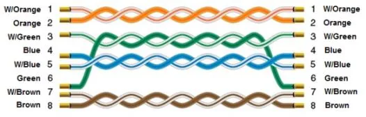
Ethernet Cable