Introduction
All Maple Systems HMI+PLCs (HMCs) programmed with MAPware7000 are compatible with Modbus RTU Master (Client). Configure your Controller and HMI+PLC (HMC) with the following parameters to establish reliable communication.
Applies to: MAPware7000
Overview
Maple Systems HMI + PLCs (HMC) communicate with any device that uses the Modbus RTU protocol. The HMC uses the Modbus RTU (Unit as a Master) protocol driver to allow the Maple HMC to act as the master in a single master, single slave or multiple slave format. RS485 networking is supported to connect multiple Modbus Slave devices to a single Maple HMC.
For more information on adding tags and using Modbus data in logic, see Tech Note 7016 – Modbus
Communication in MAPware-7000.
HMI+PLC Settings
This document lists the communications settings that must be configured in MAPware7000. These settings can be found in the Network Configuration folder for the selected project in the Project Information window:
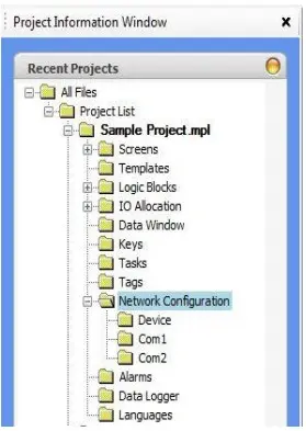
Right-click the Com port that you will use to connect to the slave device, and then click Add… to display the Node Information dialog box:
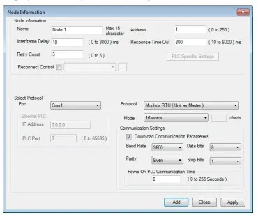
Network Settings
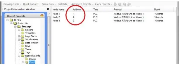
If you are connecting multiple PLC/Controllers on a network to an HMC, you can configure multiple devices (nodes) in the Network Configuration > Com1 (or Com2) folder. Assign a different Node Address to each node. Tags can be created for each node in the Tags folder
Adding Tags
PLC tags are added to the project in the tag folder after configuring the device. Select the Tags folder from the Project Information Window. Right click in the tag list and select Add… from the context menu. Select the Node Name at the top of the Add Tag dialog to specify the target device, enter a name for the tag and select the register/coil type to match what is in your controller and an address for the register. Click the Add button to save the tag to the tag list.
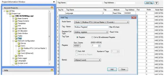
For more information on adding tags and using Modbus data in logic, see Tech Note 7016 – Modbus
Communication in MAPware-7000.
NOTE: The Recommended Settings column is blank since the Modbus RTU Slave Protocol can be used with any controller supporting Modbus RTU Master. The available port may determine whether RS-232 or RS-485 should be used.
The Options column lists MAPware7000 options; your PLC may not support every option
| Name | Recommended Setting | Options | Important Notes |
|---|---|---|---|
| Port | No recommended option | COM1, COM2 | This is the HMC port that the PLC is connected to |
| Protocol | Modbus RTU (Unit as Master) | Select the appropriate protocol for your PLC | |
| Model | 16 word 1 word | Uses FC Code:16 Uses FC Code: 6 (4x regs) | |
| Communication Setting: Baud Rate | 19200 | 4800, 9600, 19.2k, 38.4k, 57.6k, 115.2k, 187.5k | Must match the PLC serial port |
| Communication Setting: Parity | None | None, Even, Odd | Must match the PLC serial port |
| Communication Setting: Data Bits | 8 | 7, 8 | Must match the PLC serial port |
| Communication Setting: Stop Bits | 2 | 1, 2 | Must match the PLC serial port |
| Power On PLC Communication Time | No recommended option | 0-255 seconds | Delays communications with the PLC after applying power to the HMC |
| Node Information: Name | No recommended option | Maximum of 15 characters | Provide a meaningful description to the port |
| Node Information: Address | 1 | 0 to 255 | Assigns a network address to each PLC. Use when networking several PLCs on one COM port. |
| Node Information: Inter frame Delay | No recommended option | 0 to 3000 msec | Minimum time delay between commands sent to the PLC |
| Node Information count | No recommended option | 0 to 5 | The maximum attempts by the HMC to resend unanswered command. |
| Node Information: Response Time Out | No recommended option | 10 to 6000 msec | The time that must pass before the HMC reattempts to send an unanswered command to the PLC |
Connected Device Settings
The Modbus port on the slave device must be set to RTU slave mode in order to properly communicate with the HMC Master.
PLC Addressing
The following table lists the Modbus memory ranges that are accessible by the Maple HMC Series. Please note that your connected device’s memory range may be smaller or larger than that supported by the HMC. The following addresses can be displayed in 8, 16, or 32 bit formatting and/or single bit format as designated.
| PLC Address Types | Address Range | Modbus Address | Write access |
|---|---|---|---|
| Coils (0x) | bbbbb: 1-65536 | 000001-065536 | Read/Write |
| Input Coils (1x) | bbbbb: 1-65536 | 100001-165536 | Read only |
| Input Registers (3x) | bbbbb: 1-65536 | 300001-365536 | Read only |
| Holding Registers (4x) | bbbbb: 1-65536 | 400001-465536 | Read/Write |
Important Memory Considerations
If your slave device memory range is smaller than the range supported by the Maple HMC it is possible to configure the unit to monitor slave memory addresses that are not available. Because this can cause unpredictable results, when you configure the Master Device, ensure that all selected slave memory addresses are valid for your slave device.
Do not configure the Master Device to write to any PLC memory address that should only be written to
by the PLC.
Wiring Diagram
The Maple HMC serial port connects directly to the communication port on the Slave Device.
WARNING If your communications cable is not wired exactly as shown in our cable assembly instructions, damage to the HMC or loss of communications can result.
Physical Port: 4.3″ Models
COM1: The 4.3″ models have 1 physical COM port that supports RS232 and RS485
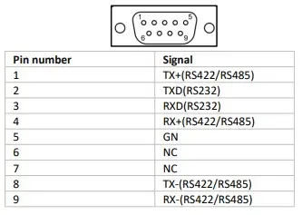
Physical Ports: 7.0″ Models
Physical Ports: 7.0″ Models
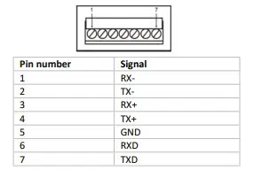
COM2: DE9 Female Port – RS232 / RS485
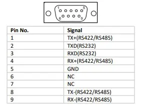
Physical Ports: 10.1″ Models
COM1 & COM2: The 10.1″ models have 2 physical COM ports that both supports RS232 and RS485
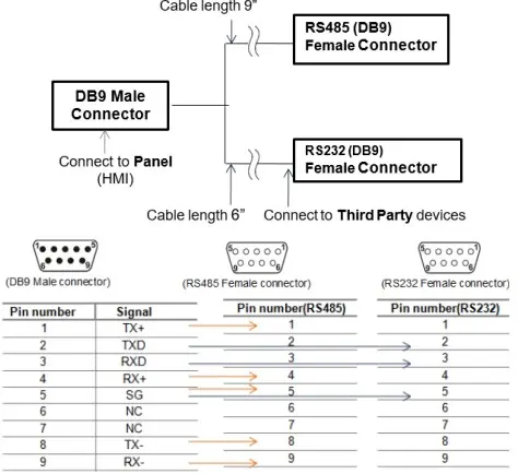
Y Type Cable (all models)
Special “Y” cable for HMC unit (two communication levels on one port)
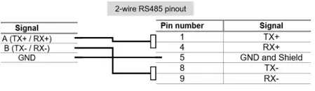
RS-485 – 2 Wire (all models)
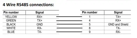
RS-485 – 4 Wire (all models)