
Introduction
All Maple Systems HMI+PLCs (HMCs) programmed with MAPware7000 are compatible with Modbus TCP/IP Slave (Server) Ethernet. Configure your Controller and HMI+PLC (HMC) with the following parameters to establish reliable communication.
Applies to: MAPware7000
Overview
MAPware7000 supports Modbus TCP/IP Ethernet. Maple Systems HMI + PLC (HMCs) communicate with any device that uses the Modbus TCP/IP Ethernet protocol. The HMC uses the Modbus RTU (Unit as Slave) protocol driver to allow the Maple device to act as a slave in a single master, single slave or multiple slave format.
HMI+PLC Settings
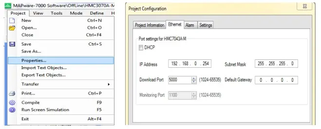
The HMC must be configured with an IP address that is accessible from the Modbus TCP/IP Master Device. The IP address is configured on the Ethernet tab of the Project Configuration window (Project > Properties…)
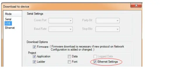
The Ethernet settings are downloaded to the HMC by checking the Ethernet Settings checkbox in the download window.
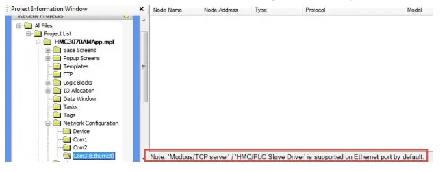
In MAPware7000 the Modbus TCP Slave (Server) driver is supported on the Ethernet port by default. Once the IP address for the unit has been set, no extra driver configuration is necessary.
Connected Device Settings
- The Modbus port on the controller must be set to TCP master mode in order to properly communicate with the HMC slave.
- The Modbus master device must be configured with an IP address that is addressable by the HMC.
- The HMC/PLC will respond on TCP port 502
In IEC 61131-3 projects, a Modbus address must be manually assigned to each tag in the Tag Database.
To access the Tag Database go to Define > Tag Database, or click on the Tags folder in the project tree.
Assign the Modbus address in the Ethernet column of the Tag Database.
NOTE: Read Write access will be specified in the tag database. Most tags are Read/Write, tags defined for input modules and some system tags will be Read Only.
| Data Types | Length | Modbus Address Range | Notes |
|---|---|---|---|
| DINT, DWORD, REAL, TIME, UDINT | 2 Words (32-bits) | 400001 – 465534 | Note 1 |
| INT, Retentive Registers, WORD, UINT | 1 Word (16-bits) | 400001 – 465535 | |
| BYTE, SINT, USINT | 1 byte (8-bits) | 400001 – 465535 | Note 2 |
| BOOL | 1-bit | 000001 – 065535 |
NOTE 1: 32-bit types require two Modbus registers. The tag occupies the specified address and the next consecutive address. Tag addresses cannot overlap.
NOTE 2: 8-bit types require one Modbus address per tag. The data will reside in the low word of the register
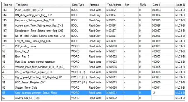
Important note: Most Modbus Master Devices read blocks of data at a time; it is good practice to assign consecutive Modbus addresses when using IEC Mode.
Important Memory Considerations
If your PLC memory range is smaller than the range supported by the Master Device, it is possible to configure the unit to monitor PLC memory addresses that are not available. Because this can cause unpredictable results, when you configure the Master Device, ensure that all selected PLC memory addresses are valid for your PLC model.
Do not configure the Master device to write to any PLC memory address which should only be written to by the PLC.
Wiring Diagram
The Maple HMC Ethernet port connects directly to the Modbus TCP/IP Ethernet port on the Modbus master device.
WARNING If your communications cable is not wired exactly as shown in our cable assembly instructions, damage to the HMC or loss of communications can result.
Ethernet Port (all models)
- Fully compliant with IEEE 802.3 / 802.3u standards.
- 10/100Mbps support.
- Connector used: Standard shielded RJ-45 female jack with in-built speed and link activity indication LEDs.
- Default IP Address: 192.168.0.254
- Default Subnet Activity Mask: 255.255.255.0
| Pin Number | Signal |
|---|---|
| 1 | TX+ |
| 2 | TX- |
| 3 | RX+ |
| 4 | NC |
| 5 | NC |
| 6 | RX- |
| 7 | NC |
| 8 | NC |