
Introduction
All Maple Systems HMIs programmed with EBPro (EasyBuilder Pro), including every cMT X Series and cMT Series model, are compatible with a Mitsubishi QJ71E71 (Ethernet). Configure your Controller and HMI/cMT with the following parameters to establish reliable communication.
Supported Series ; Mitsubishi Q type, MELSEC-Q series PLC (Q00J, Q00, Q01, Q02, Q02H, Q06H, Q12H, Q25H, Q12PH, Q25PH) QJ71E71-100 Ethernet module.
Website: http://www.mitsubishi-automation.com
HMI Settings
| Parameters | Recommended | Options | Notes |
|---|---|---|---|
| PLC type | Mitsubishi QJ71E71 (Ethernet) | ||
| PLC I/F | Ethernet | ||
| Port no. | 5002 | ||
| PLC sta. no. | 2 | 1~99 | |
| Network | 1 | 1~999 |
PLC Setting
QJ71E71-100 Ethernet module settings:
Open Network Parameters in GX Developer
Use USB or RS232 of Q-CPU for setting PLC parameters. Open Network parameters under the Parameter node in the project tree.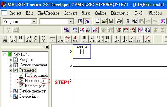
Click Operational Settings
In the Network parameter dialog, select Ethernet/CC IE/MELSECNET and configure the module: set Network type to Ethernet, assign Network No. and Station No., then click Operational settings.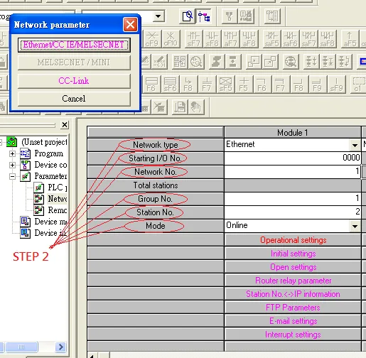

Select Ethernet (V2.0) and Set IP Address
In the Ethernet operations dialog, set Send frame setting to Ethernet(V2.0) for communicating with HMI. Set the IP address in DEC format (e.g., 192.168.10.105).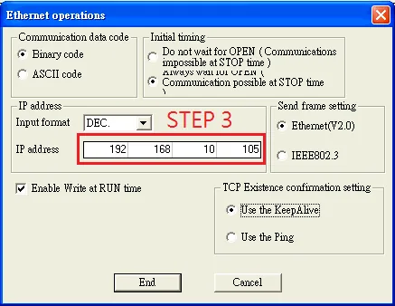
Click Open Settings
Back in the network parameter panel, click Open settings to configure TCP/UDP port parameters.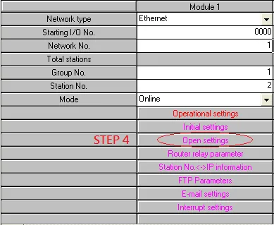
TCP Port Settings
Set Open System to Unpassive.

UDP Port Settings
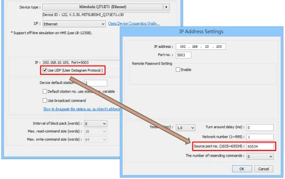
EBPro (EasyBuilder Pro) Version 6.03.02.493 Build 2020.04.30 up to (excluding) Version 6.04.01.373 Build 2020.04.30:
Only communication ports 5000 and 5001 can be used (no configuration required).
EBPro (EasyBuilder Pro) Version 6.04.01.373 Build 2020.04.30 (inclusive) and later versions:
Support all UDP Port settings shown below.

Configure GX Developer Connection
Press END to Finish Settings
Press END to complete the Open settings and finalize the Ethernet module configuration.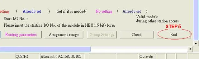
Restart PLC Software and Read from PLC
Restart PLC software and select READ FROM PLC, then select QCPU(Qmode) and press OK.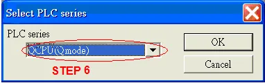
Set Network No. and Station No. in PC Side I/F
In PC side I/F Ethernet board setting, set Network No. and Station No. Station No. 1 is the PC Station No., not the Ethernet module Station No. (range 2–64). The Network No. cannot be the same as that of the PC.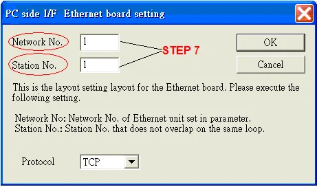
Set QJ71E71 IP Address in PLC Side I/F
Select Ethernet module in PLC Side I/F to set the QJ71E71 IP address. The IP address must match the Network Parameter IP address (e.g., 192.168.10.105).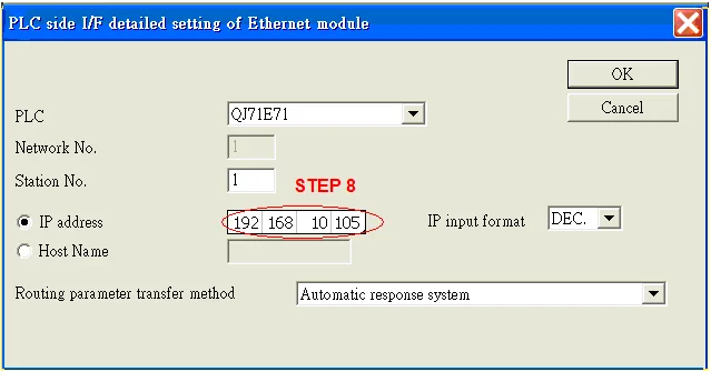
Configure Other Station Settings
For Other station, click Other station (Single network) to set Check at communication time and Retry times.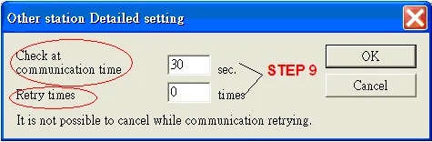
Run Connection Test
After finishing the settings above, click Connection test to test the communication and send the PLC program.
Device Addresses
| Bit/Word | Device Type | Format | Range | Memo |
|---|---|---|---|---|
| B | SM | N.DDDD | 0 ~ 4.2047 | |
| B | X | N.HHHH | 0 ~ 4.1fff | Input Relay |
| B | Y | N.HHHH | 0 ~ 4.1fff | Output Relay |
| B | M | N.DDDDD | 0 ~ 4.61439 | Internal Relay |
| B | L | N.DDDDD | 0 ~ 4.32767 | Latch Relay |
| B | F | N.DDDDD | 0 ~ 4.32767 | Annunciator |
| B | V | N.DDDDD | 0 ~ 4.32767 | Edge Relay |
| B | B | N.HHHH | 0 ~ 4.1fff | Link Relay |
| B | TS | N.DDDD | 0 ~ 4.2047 | Timer Contact |
| B | TC | N.DDDD | 0 ~ 4.2047 | Timer Coil |
| B | SS | N.DDDDD | 0 ~ 4.25471 | Retentive Timer |
| B | SC | N.DDDDD | 0 ~ 4.25471 | Retentive Timer Coil |
| B | CS | N.DDDDD | 0 ~ 4.25471 | Counter Contact |
| B | CC | N.DDDDD | 0 ~ 4.25471 | Counter Coil |
| B | SB | N.HHH | 0 ~ 4.7ff | Special Link Relay |
| B | S | N.DDDD | 0 ~ 4.8191 | Step Relay |
| B | DX | N.HHHH | 0 ~ 4.1fff | Direct Input |
| B | DY | N.HHHH | 0 ~ 4.1fff | Direct Output |
| B | D_Bit | N.DDDDDDDh | 0 ~ 4.4212735f | |
| B | ZR_Bit | N.HHHHHh | 0 ~ 4.fe7fff | |
| B | ZR_Dec_Bit | N.DDDDDDDh | 0 ~ 4.1042431f | |
| W | SD | N.DDDD | 0 ~ 4.2047 | |
| W | D | N.DDDDDDD | 0 ~ 4.4212735 | Data Register |
| W | W | N.HHHH | 0 ~ 4.1fff | Link Register |
| W | TN | N.DDDD | 0 ~ 4.2047 | Timer Current Value |
| W | SN | N.DDDD | 0 ~ 4.2047 | Retentive Timer Current Value |
| W | CN | N.DDDD | 0 ~ 4.1023 | Counter Current Value |
| W | SW | N.HHH | 0 ~ 4.7ff | Special Link Register |
| W | Z | N.DD | 0 ~ 4.15 | Index Register |
| W | R | N.FFFDDDDD | 0 ~ 4.3132767 | File Register (FF: File No. 0~31, DDDDD: 0~32767) |
| W | ZR | N.HHHHH | 0 ~ 4.fe7ff | File Register |
| W | ZR_decimal_addr | N.DDDDDDD | 0 ~ 4.1042341 |
NOTE: N = CPU Slot no. (0~4)
Wiring Diagram
The diagram below shows the Ethernet cable wiring.
