Introduction
All Maple Systems HMIs programmed with EBPro (EasyBuilder Pro), including every cMT X Series and cMT Series model, are compatible with a Mitsubishi MELSEC-Q/L ASCII Mode (Ethernet). Configure your Controller and HMI/cMT with the following parameters to establish reliable communication.
Supported Series: Mitsubishi Q series (Q03UDE, Q04UDEH, Q06UDEH, Q10UDEH, Q13UDEH, Q20UDEH, Q26UDEH, Q002UD), Mitsubishi L series(L02, L26-BT), MELSEC-Q/L protocol application to CPU of Ethernet interface or Ethernet module.
Website: http://www.mitsubishi-automation.com
HMI Settings
| Parameters | Recommended | Options | Notes |
|---|---|---|---|
| PLC type | Mitsubishi MELSEC-Q/L – ASCII Mode (Ethernet) | ||
| PLC I/F | Ethernet | ||
| Port no. | 4999 | 1025 to 4999 or 5010 to 65534 | |
| Network number | 0 | 0~255 | |
| PLC sta. no. | 255 | 255 | |
| Protocol | TCP | TCP / UDP | MC Protocol |
| Online simulator | YES |
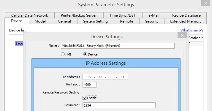
Remote Password Setting
Set a remote password and a target connection in the engineering tool, and write the data to the CPU module.
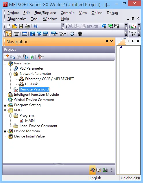
Navigation Window => [Parameter] => [Remote Password] => [Remote Password Setting] Screen
PLC Settings
MITSUBISHI Q/L Series Ethernet Module Setting
NOTE: Check “Enable online change (FTP, MC protocol)”
NOTE: If using QJ71E71 module, please refer to MITSUBISHI QJ71E71 connection guide.
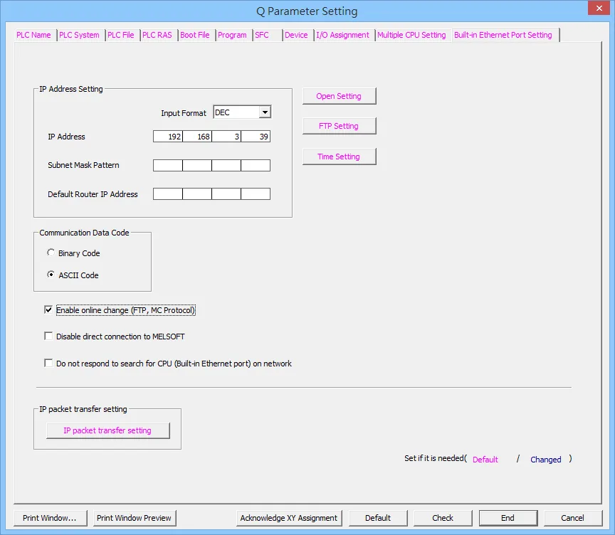
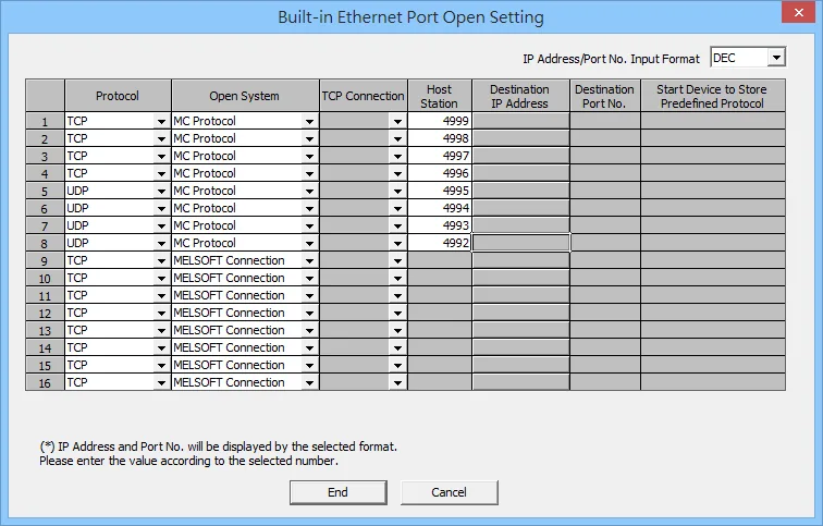
Configure the Built-in Ethernet Port Open Setting as follows:
- Protocol: TCP or UDP
- Open System: MC Protocol
- Host Station: 1025 to 4999 or 5010 to 65534
Import Tags:
The Mitsubishi Ethernet tag import accepts symbol files with extension “csv” created by the Mitsubishi GX Works2 (Not from GX Developer).
The “.csv” file can be exported from the Project tree.
- Right-click on the Global variable list that need to be exported.
- Select “Write to CSV File…”
- Select the file name and location.
- Open EBPro (EasyBuilderPro) -> System Parameter Settings
- Click “Import Tags…”
- Select the CSV File.
- Check the imported tags.
- Import tag information successfully.
Device Address
| Bit/Word | Device Type | Format | Range | Memo |
|---|---|---|---|---|
| B | SM | DDDD | 0 ~ 2047 | Special Relay |
| B | X | HHHH | 0 ~ 1fff | Input Relay |
| B | Y | HHHH | 0 ~ 1fff | Output Relay |
| B | M | DDDDD | 0 ~ 61439 | Internal Relay |
| B | L | DDDDD | 0 ~ 32767 | Latch Relay |
| B | F | DDDDD | 0 ~ 32767 | Annunciator |
| B | V | DDDDD | 0 ~ 32767 | Edge Relay |
| B | B | HHHH | 0 ~ efff | Link Relay |
| B | TS | DDDDD | 0 ~ 25471 | Timer Contact |
| B | TC | DDDDD | 0 ~ 25471 | Timer Coil |
| B | SS | DDDDD | 0 ~ 25471 | Retentive Timer Contact |
| B | SC | DDDDD | 0 ~ 25471 | Retentive Timer Coil |
| B | CS | DDDDD | 0 ~ 25471 | Counter Contact |
| B | CC | DDDDD | 0 ~ 25471 | Counter Coil |
| B | SB | HHHH | 0 ~ 7fff | Special Link Relay |
| B | S | DDDD | 0 ~ 8191 | Step Relay |
| B | DX | HHHH | 0 ~ 1fff | Direct Input |
| B | DY | HHHH | 0 ~ 1fff | Direct Output |
| B | D_Bit | DDDDDDh | 0 ~ 999999f | Data Register Bit |
| B | SD_bit | DDDDh | 0 ~ 2047f | Special Register Bit |
| B | ZR_bit | DDDDDDh | 0 ~ 999999f | File Register Bit |
| B | R_bit | DDDDDh | 0 ~ 32767f | File Register Bit |
| B | SW_bit | HHHh | 0 ~ 7fff | Special Link Register Bit |
| B | W_bit | HHHHHHh | 0 ~ 3fd7fff | Link Register Bit |
| W | SD | DDDD | 0 ~ 2047 | Special Register |
| W | D | DDDDDD | 0 ~ 999999 | Data Register |
| W | W | HHHHHH | 0 ~ 3fd7ff | Link Register |
| W | TN | DDDDD | 0 ~ 25471 | Timer Current Value |
| W | SN | DDDDD | 0 ~ 25471 | Retentive Timer Current Value |
| W | CN | DDDDD | 0 ~ 25471 | Counter Current Value |
| W | SW | HHH | 0 ~ 7ff | Special Link Register |
| W | Z | DD | 0 ~ 20 | Index Register |
| W | R | DDDDD | 0 ~ 32767 | File Register |
| W | ZR | DDDDDD | 0 ~ 999999 | File Register |
NOTE: Each model of CPU is different; it is recommended to refer to the MITSUBISHI MELSEC-Q Manual Device List.
Wiring Diagram
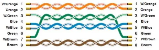
NOTE: Connect HMI to PLC using a standard Ethernet straight-through cable (CAT5e or CAT6).
The diagram below shows the Ethernet cable wiring.