This tutorial demonstrates how to configure Modbus TCP communication between two Maple Systems PLCs. In this example, a Maple Modular PLC operates as the Modbus TCP Master, while a Maple Micro PLC functions as the Modbus TCP Slave. Communication is established using the MOD-SENT01 Ethernet module.
By following this guide, you will learn how to configure network settings, set up Modbus registers, and verify communication between the PLCs using MapleLogic programming software.
Software Required
Hardware Required
Note: Maple Modular PLCs support Modbus TCP Master functionality when used with the MOD-SENT01 Ethernet module.
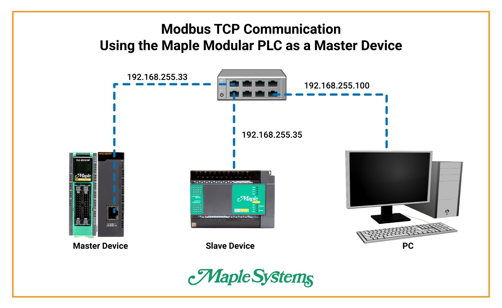
Modbus TCP Network Configuration

Both PLCs should be connected through an Ethernet switch. Ensure that each device uses the same subnet while maintaining a unique IP address for each controller.
Configure Modbus TCP Master (Maple Modular PLC)
Create a Modbus TCP master program and configure the slave device communication.
Instructions: Configure Modbus TCP Master (Maple Modular PLC)
Create a Modbus TCP Master Program
Right-click on Program → Select New Program → Choose MODBUS/TCP MASTER → Name the program → Assign an ID number → Click OK.

Add the Slave Device IP Address
In the Special Function window click New → Enter the IP address of the Maple Micro PLC → Ensure the device is on the same subnet as the master PLC → Click OK → Set Slot to Slot 1 for the Ethernet module → Click Save.

Create a Data Block for Register Reading
Click Add → Select function 03 Read Holding Registers (4x) → Assign PLC register D00 as the destination register → Click Save.

Configure the Master PLC Ethernet Settings
Open PLC Parameter → Select the Ethernet tab → Enter the Modbus TCP Master IP address → Ensure it shares the same subnet as the slave device → Click OK.

Configure the MOD-SENT01 Ethernet Module
Connect online to the PLC → Select Slot 1 for the Ethernet module → Verify the IP address matches the master configuration → Set Modbus Unit ID to 1 → Click Write to apply settings.

Configure Modbus TCP Slave (Maple Micro PLC)
Set up the analog input channel and configure the slave PLC network settings.
Instructions: Configure Modbus TCP Slave (Maple Micro PLC)
Configure the Analog Input Channel
Open PLC Parameter → Select the Analog I/O tab → Change device register to D0 → Enable Analog Input Channel 1 → Set the input type to 0-5V → Click OK.

Configure the Slave PLC IP Address
Open PLC Parameter → Select the Ethernet tab → Enter the Modbus TCP Slave IP address → Ensure it is on the same subnet as the master PLC → Click OK.

Verify Online Communication
After downloading the project to both PLCs, place the controllers into RUN mode and monitor communication online in MapleLogic. The master PLC should read the configured registers from the slave PLC.


Sample Project
The following sample projects demonstrate the configuration shown in this tutorial and can be used as a reference when building your own application.
- Download MapleLogic Sample Project (Slave Device)
- Download MapleLogic Sample Project (Master Device)
Resources & Documentation
- MapleLogic User Manual
- Maple Modular PLC User Manual
- Maple Micro PLC User Manual
- Ethernet Module Manual
Looking for more learning resources?
Visit the Support Center for additional manuals, installation guides, and technical documentation.
About the Author
Trusted source for industrial automation & control solutions
Follow Maple Systems:
Share:


