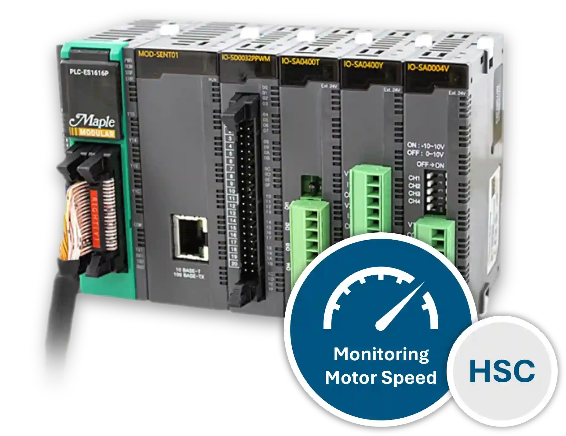
This tutorial will cover the configurations using the built-in High Speed Counter for the Maple PLC’s and determining motor speed using a Quadrature Encoder in the control software (MapleLogic).
Software Required
Hardware Required
- Maple Modular PLC’S – Any Maple Modular PLC can be used.
- Maple Micro PLC’S – Any Maple Micro PLC can be used.
- Two-Phase Quadrature Encoder
- 12-24 VDC Motor
- PWM Brush Motor Speed Controller
- 24 VDC Power Supply (4010-0011)
High Speed Counter Setup
This section covers the wiring, configuration, ladder logic, online monitoring, and live simulation used to measure motor speed with the built-in High Speed Counter in MapleLogic.
Wiring and Circuit Design
Use the following diagrams to connect the encoder and PLC inputs for this High Speed Counter example.
Instructions: Wiring and Circuit Design
Review the main wiring diagram
Use the wiring diagram below to connect the encoder, motor, and PLC for this example setup.

Verify the PLC input terminals
Use the terminal diagram below to confirm the correct PLC input connections for the High Speed Counter signals.

High Speed Counter Configuration
Configure the built-in High Speed Counter in MapleLogic to read a two-phase quadrature encoder and calculate RPM.
Instructions: High Speed Counter Configuration
Select the counter mode
In this sample, select a Linear Counter to count in one direction.
Select the input pulse type
Because this example uses a 2 Phase Quadrature Encoder, select “2 Phase, 4 Multiplication” as the Input Pulse Type.
Set Unit Time
Enter 1000 for Unit Time based on the number of pulses the encoder outputs in one revolution.
Set Pulse per 1 Cycle
Enter 1000 for Pulse per 1 Cycle, since this example uses 1000 pulses per rotation.
Set RPM or PPS mode
Set RPM to 1. If you want to read pulses per second instead, enter 0 for PPS.
Ladder Diagram
Create ladder logic to enable the RPM flag and turn on an alarm when motor speed reaches the configured threshold.
Instructions: Ladder Diagram
Review the ladder diagram
Use the following ladder diagram as the basis for the High Speed Counter logic.

Enable the RPM flag
Use an ALWAYS_ON bit on the first rung to turn on the RPM Flag. This must be enabled to use RPM in the High Speed Counter configuration.
Locate the RPM status flag in MapleLogic Help
In the MapleLogic Help file, navigate to Built In High Speed Counter, then go to Parameters and scroll to the control bits. Look for register 16, Bit 5 for the RPM Status Flag.

Calculate the correct address
Because the starting address is D100, add 16 to get D116. Bit 5 makes the full address D116.5, so the application instruction is [SET D116.5].

Add the alarm compare instruction
On the second rung, use a compare instruction to turn on alarm output Y10 when motor speed is greater than or equal to 1800 RPM.
High Speed Counter Online
Download the project to the PLC and monitor the High Speed Counter while the system is running.
Instructions: High Speed Counter Online
Go online and download the project
Download the project to the PLC and open the ladder diagram online view.

Enable the counter
Check “Enable Count” to initiate the High Speed Counter. This must be checked for the counter to operate.
Verify the RPM bit is enabled
Confirm that F10 is ON and turns on [SET D116.5] to enable the “ON : RPM” bit.
Monitor the High Speed Counter
Click “Monitor” to view the High Speed Counter while online.

Confirm counter status
After pressing Monitor, verify that both the “Enable Count” flag and the “ON : RPM” flag are turned on.
Live Simulation of High Speed Counter and Motor
Observe how the High Speed Counter reacts to motor speed changes, alarm thresholds, and reverse rotation.
Instructions: Live Simulation of High Speed Counter and Motor
Observe encoder inputs with speed below the alarm threshold
In the live camera view, X00 and X01 are ON for the encoder Phase A and Phase B wires. The motor speed is below 1800 RPM, so alarm Y10 remains OFF.

Observe alarm activation above 1800 RPM
When the motor speed exceeds 1800 RPM, alarm Y10 turns ON. In the live camera feed, the red LED indicates the alarm output is active.

Observe alarm reset below 1800 RPM
When the motor speed drops back below 1800 RPM, alarm Y10 turns OFF again.

Observe reverse rotation and down count
A 2 Phase Quadrature encoder can count in both forward and reverse directions. When the motor runs in reverse, a negative RPM value appears in the ladder logic and the Down Count status flag turns ON.

High Speed Counter I/O Module
If your application needs more High Speed Counter channels than the PLC provides, you can add an expansion module. Maple Systems offers the IO-SHSC02 High Speed Counter Module for this purpose.
The IO-SHSC02 adds encoder input capability to Maple Modular PLC systems and gives you more flexibility when your application requires additional counter channels.
- Add the IO-SHSC02 when you need more High Speed Counter channels.
- Use this module with Maple Modular PLC systems.
- Each module provides two High Speed Counter channels, similar to the built-in counters available in Maple Modular and Micro PLCs.
- The module includes the same counter features and configuration options as the built-in High Speed Counter.
- Use a terminal block to connect the encoder wiring to the module.
Refer to the High Speed Counter Module documentation for wiring examples and connection details before installation.


Refer to the High Speed Counter Module User Manual for detailed wiring examples and connection diagrams when installing the module.
Sample Project
This integration tutorial uses these MapleLogic sample project.
Resources & Documentation
The following guides and documentation are specific to the hardware used in this integration tutorial and will help you with setup, configuration, and programming:
- MapleLogic User Manual
- Maple Modular User Manual
- Maple Micro User Manual
- High Speed Counter Module User Manual
Looking for additional learning resources? Explore our library of tutorials, example projects, and software tools to help you get the most out of your system:
Also, browse our Support Center for a complete list of installation guides, FAQs, and additional technical documentation.
About the Author
Trusted source for industrial automation & control solutions
Follow Maple Systems:
Share:


