A Variable Frequency Driver (VFD) controls the speed and other parameters of an AC induction motor. VFDs are also known as variable speed drives, adjusted frequency drives, AC drives, and inverters. In this guide, you will learn how to connect a Maple HMI, a Maple PLC, and a VFD to build a simple motor control system. You will configure Modbus communication between all three devices and use data registers to control motor speed and direction.

Software Required
- EBPro (HMI programming software)
- MapleLogic (PLC programming software)
Hardware Required
- Any Maple Systems HMI
- Any Maple Systems PLC (a Modular PLC is used in this example)
- Any VFD with Modbus RTU support (a Yaskawa GA500 is used in this example)
Getting Started with VFDs
VFDs are used in industry to control machinery such as fans and pumps in HVAC systems, mixers and conveyor belts in manufacturing, and other industrial plant equipment. When an application requires overload protection, flexible load control, and efficiency management to extend motor life, a VFD is a strong choice. By adjusting frequency along with acceleration and deceleration parameters, motors can ramp to speed in a controlled and safe manner.
Digital and Analog Inputs and Outputs
Most VFDs have digital and analog I/O terminals for adjusting frequency output, start/stop commands, and more. These terminals can be wired to a PLC’s I/O for dynamic control, or to physical buttons, potentiometers, and indicator lights on a control panel.
Communication Protocol
A VFD can be controlled by other devices over various communication protocols. The most common protocol among VFD manufacturers is Modbus. Similar to how a smartphone controls Wi-Fi connected devices using a wireless protocol, a PLC or HMI can send and receive commands to a VFD over Modbus.
Direct Keypad Control
If your VFD has a built-in keypad, you can configure all parameters — including voltage, frequency, and run commands — directly from the drive. This method works but is the least convenient option for ongoing operations.
Combination
Most real-world systems use a combination of control methods. For example, you may control the VFD with a PLC while also keeping physical emergency controls wired directly to the drive.
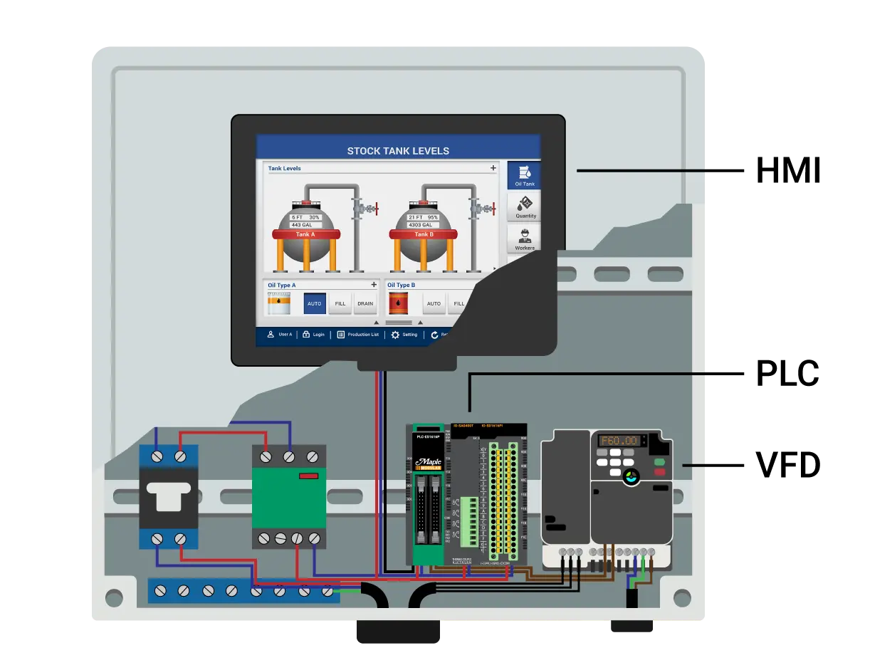
In this guide, we use a Maple HMI, a Maple PLC, and a VFD to demonstrate a simple motor control system that incorporates visual controls, PLC logic, and multi-device communication.

The HMI visualizes VFD operations and sends control instructions to the PLC over Modbus TCP/IP. The PLC receives those commands, runs logic based on the input, and sends run commands to the VFD over Modbus RTU.
Configuring the VFD
Configuring a VFD generally involves three steps:
- Select and enable the desired communication protocol
- Adjust the parameters of the communication protocol
- Map the registers needed to control the motor
Every VFD is configured slightly differently, so refer to the manufacturer’s documentation for specific wiring and setup requirements.
This example uses Modbus RTU over RS-485 with the drive set to node address 1, communication speed 9600bps, and no parity.
Below are the settings and wiring details for the VFDs supported in this guide:
Yaskawa GA500
Parameters:
Enable Modbus Communication for Frequency and Run Commands (pg. 226)
B1-01 set to 2 (Enable Modbus Communication Control of Frequency)
B1-02 set to 2 (Enable Modbus Communication Control of Run Commands)
Set the Communication Parameters (pg. 701-702)
H5-01 set to 1 (Drive node address (Slave ID) of 1)
H5-02 set to 3 (Communication speed of 9600bps)
H5-03 set to 0 (Parity Selection of No Parity)
H5-04 set to 0 (Communication Error Stop of Ramp to Stop)
The GA500 VFD has seven multi-function digital input commands that can be used to customize motor control. Below we will set two of them to the forward and reverse jog commands.
Multi-function Digital Input Command Parameters (pg. 643)
H1-01 set to 12 (Forward Jog)
H1-02 set to 13 (Reverse Jog)
Alarm Display at External 24V Power Supply (pg. 95)
o2-26 set to 0 (Alarm Display disabled when only external 24V power supplied – “Ready” LED light will be flashing when “motor” is ready)
Wiring (and Physical Settings)

Powering the Control Circuit:
To power the external power supply used to operate the drive, without having to wire the main circuit power, we wire +24Vdc to PS terminal and the -24Vdc to the AC terminal.
Wiring Modbus RTU RS-485 Communication:
For communication between devices, the Maple PLC and the GA500 both utilize a 2-wire RS-485 connections, meaning we can directly wire D+ to D+, D- to D-, and SG (Signal Ground of PLC) to AC (GND of VFD).
Note: Set DIP switch s2 to the ON position (termination resistor for the last drive in Modbus network)
Please refer to the GA500 Manual for all configuration settings and specifications of a particular model of the VFD.
Note: The parameters listed are only meant to establish communication with the PLC and control the VFD function commands of the driver – this example does not include a motor or the motor parameter needed to be adjusted for a three-phase motor.
Allen Bradley PowerFlex 525
–
Coming Soon!
Automation Direct GS21-20P2 (w/ 1-Phase Motor)
–
Coming Soon!
After completing all configuration changes, you can determine which Modbus addresses to use to control the motor. The table below shows the Modbus addresses used to control the GA500 VFD in this example.

For example, writing a value of 6000 to the 4×3 register will update the VFD’s reference frequency to 60Hz (6000 × 0.01Hz). Turning on bit 0 of the 4×2 register will then start the motor running forward at 60Hz.
Configuring the Communication Protocols
This section walks through configuring both communication links: Modbus TCP/IP between the HMI and PLC in MapleLogic, and Modbus RTU between the PLC and VFD in EBPro.
PLC Configuration in MapleLogic
Configure Modbus TCP/IP (HMI to PLC) and Modbus RTU (PLC to VFD) communication settings in MapleLogic.
Instructions: PLC Configuration in MapleLogic
Configure Ethernet Settings
Double-click the PLC Parameter window and open the Ethernet tab. Set the IP address to 192.168.1.111. The HMI will use this address to communicate with the PLC over Modbus TCP/IP.

Set the Modbus Slave ID and RTU Parameters
In the Modbus tab, set the slave ID to 0. Then open the CH2 tab and configure the Modbus RTU parameters to match the VFD: master station number 0, 9600bps, no parity, 8-bit data, and 1 stop bit.

Create a Modbus RTU Master Program
Right-click the program tab in the project window and create a new RTU-Master Special program. Select slot 0 (CPU) and set Channel to CH2 (RS-485). Assign D0 as the run command register and D1 as the frequency reference register. Click Add to create a communication block. Configure block 0 to target slave ID 1 (the VFD) and write the value of D0 to the 4×2 register using function code 06.

HMI Configuration in EBPro
Set up Modbus TCP/IP Master communication in EBPro to connect the HMI to the PLC.
Instructions: HMI Configuration in EBPro
Configure Modbus TCP/IP Master
Open a new project in EBPro and go to System Parameters. Click “New Device/Server…” and select “Modbus TCP/IP Master”. Set the IP address to 192.168.1.111 and the device default station number to 0 to match the PLC settings.

For more information on setting up Modbus communication between a Maple PLC and HMI, see our Modbus RTU and TCP Communications tutorial.
PLC Project
The PLC program uses a simple scan program with ladder logic to control the VFD. It uses a small number of contacts, output coils, set bits, and reset bits. The program below is the complete logic used in this example.
Building the PLC Ladder Logic
Create the scan program in MapleLogic to control VFD run commands and frequency reference.
Instructions: Building the PLC Ladder Logic
Build the Ladder Logic Program
In MapleLogic, create a scan program using contacts, output coils, set bits, and reset bits to control the motor.
– Use Y100-Y104 registers for motor command conditions
– Use D0 to hold the run command word (written to VFD register 4×2)
– Use D1 to hold the frequency reference value (written to VFD register 4×3)
Add safety interlocks to prevent the motor from running forward and reverse at the same time.
Review the HMI-to-PLC Register Mapping
Use the register mapping table to confirm how HMI Modbus addresses correspond to PLC registers. The frequency reference maps directly to D001. Motor commands from the HMI map to Y100-Y104, which allows them to be used as logic conditions in the ladder program rather than writing directly to the VFD.

HMI Project
With the communication protocols set up and the PLC program built, the next step is to create the HMI screen in EBPro.
Creating the HMI Project in EBPro
Build the HMI screen in EBPro to control and monitor VFD operation.
Instructions: Creating the HMI Project in EBPro
Add a Numeric Object for Frequency Control
Go to the Object tab and click “Numeric”. Select the Modbus TCP/IP Master device and set the address to the frequency reference register (D001 on the PLC). This object lets operators enter the desired motor speed.

Add Push Buttons for Motor Commands
Click “Set Bit” to add a push button. Set the Modbus address to the appropriate motor command register (Y100-Y104 on the PLC) and select “Momentary” as the button style. Repeat this step for each command: start, stop, jog forward, jog reverse, and reverse toggle.

Complete the HMI Screen
Repeat the process to add objects for all Modbus registers. The finished HMI screen should include controls for reference frequency, start, stop, jog, and reverse toggle.

Running the Applications
With both projects complete, wire up all devices, supply power, and download the programs to your HMI and PLC. Once both devices are running, use the HMI to send frequency and run command values to the PLC. The PLC processes those commands through its ladder logic and sends the corresponding run instructions to the VFD over Modbus RTU.
Sample Project
This tutorial uses these downloadable HMI and PLC sample projects to recreate the VFD demo application described in this guide.
Video Tutorial
For a step-by-step video guide on connecting a Maple HMI to a Maple PLC, watch the tutorial below. It covers both Ethernet and serial communication and demonstrates how to create HMI and PLC projects from scratch.
How to Set Up your Maple PLC and Maple HMI using Modbus RTU and TCP Communications
Resources & Documentation
The following guides and documentation are specific to the hardware used in this tutorial and will help with setup, configuration, and programming:
Looking for additional learning resources? Explore our library of tutorials, example projects, and software tools to help you get the most out of your system:
Also, browse our Support Center for a complete list of installation guides, FAQs, and additional technical documentation.
About the Author
Trusted source for industrial automation & control solutions
Follow Maple Systems:
Share:


