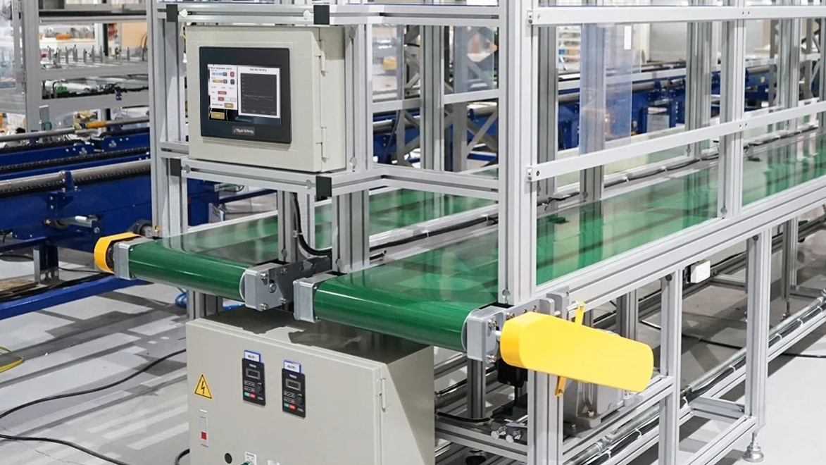
Imagine you’re in charge of adding a section of conveyor belt to an existing assembly line. You know that your conveyor belt will include a motor that needs to move at variable speeds. You also want to ensure that you’re able to implement soft start and stop to ensure this conveyor belt lasts as long as possible. Controlling a VFD with our Maple Systems HMC would serve as an excellent solution for this.

Software Required
Hardware Required
- Any Maple Systems HMC combo unit
- A VFD that can communicate over Modbus (I’ll be using a Yaskawa GA500 for this example)
Initial Configuration
For this example, I’ll be wiring my VFD over a Modbus RTU connection. But we can also use this same project, and same configuration over a Modbus TCP/IP connection as well.
Configuring and Wiring the VFD
To start, we’ll wire up and configure our VFD. This process will vary depending on the VFD you’re using, we’ll demonstrate the setup for a Yaskawa GA500 in this tutorial.
Instructions: Configuring and Wiring the VFD
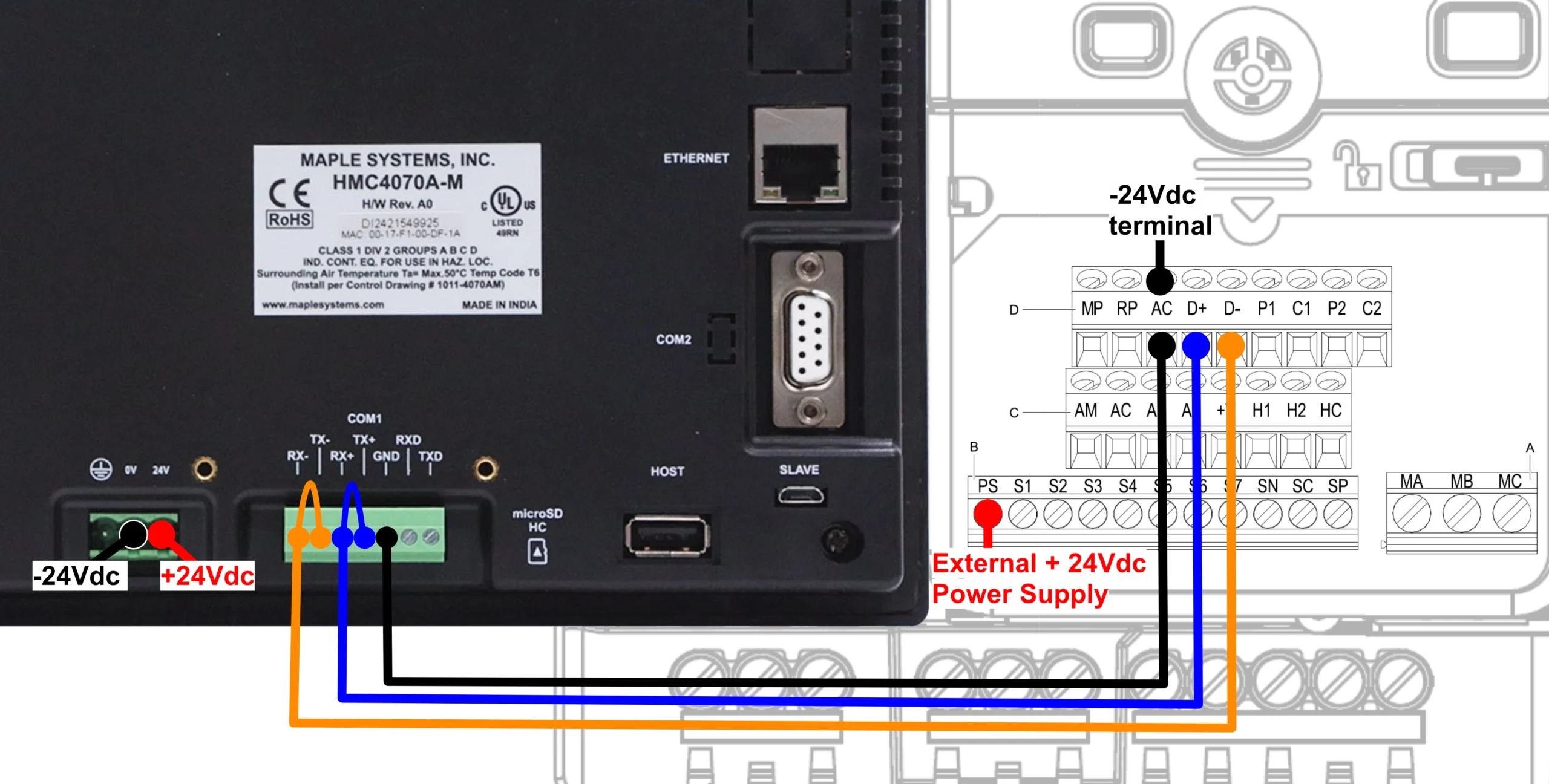
Wiring our Devices
To start, we’ll be sure to wire our devices for Modbus over an RS-485 connection. Notice the cable jumps on the HMC-side between the
Enabling Modbus communication on the VFD
We’ll Power on the VFD, navigate into our parameters, and then set the following parameters:
B1-01 set to 2 (Enable Modbus Communication Control of Frequency)
B1-02 set to 2 (Enable Modbus Communication Control of Run Commands)Setting Serial Communication Parameter
Then we’ll set some of the H5 parameters to specify our serial settings:
H5-01 set to 1 (Drive node address (Slave ID) of 1)
H5-02 set to 3 (Communication speed of 9600bps)
H5-03 set to 0 (Parity Selection of No Parity)
H5-04 set to 0 (Communication Error Stop of Ramp to Stop)Multi-function Digital Inputs
The GA500 VFD has seven multi-function digital input commands that can be used to customize your motor controls. We’ll set two of them to enable forward and reverse jog commands.
H1-01 set to 12 (Forward Jog)
H1-02 set to 13 (Reverse Jog)Alarm Display at External 24V Power Supply
Finally we’ll configure our LED display the way we want it.
o2-26 set to 0 (Alarm Display disabled when only external 24V power supplied – “Ready” LED light will be flashing when “motor” is ready)
After configuring the VFD, we’ll have the following Modbus addresses tied to the following VFD controls:

Initializing the HMC Project
Next, we’ll create a new HMC project and initialize Tags for controlling our VFD.
Instructions: Initializing the HMC Project
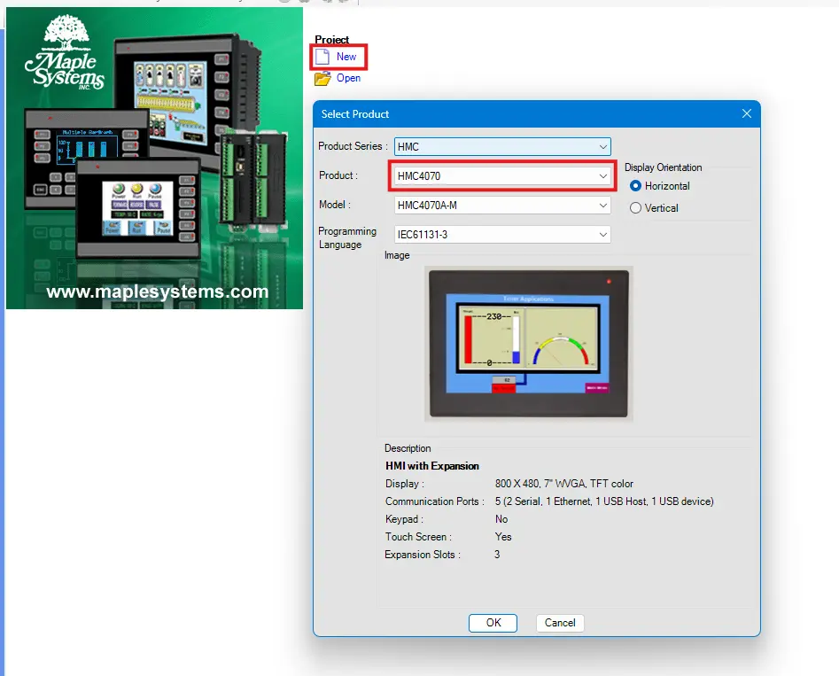
Create a new HMC project
We’ll start by creating a new MAPware-7000 project. I’ll be using an HMC4070 for this tutorial.
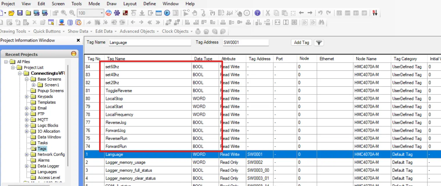
Initialize local VFD bit addresses
We’ll then navigate to the tags database and initialize a handful of tags in our local HMC associated with various controls on the VFD. We’ll want to set 4 bit addresses for forward and reverse run, as well as forward and reverse jog. Then we’ll want to create a word register for the frequency reference.
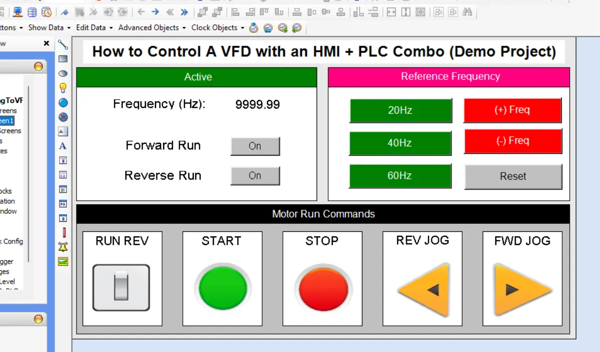
Tie our local tags to screen objects.
Now we’ll design our screen to display and control our VFD values from within our HMC project.
Connecting the HMC to VFD Modbus Addresses
Now we’ll need to further configure our logic to tie our local tags to the Modbus addresses we assigned our VFD controls to.
Instructions: Connecting the HMC to VFD Modbus Addresses
Initialize a Modbus Node in MAPware-7000
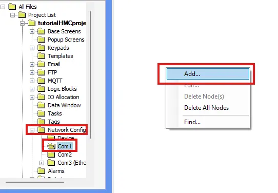
We’ll start by creating a new network node in our MAPware-7000 project by navigating to “Network Config > Com1” right clicking and selecting “Add…”
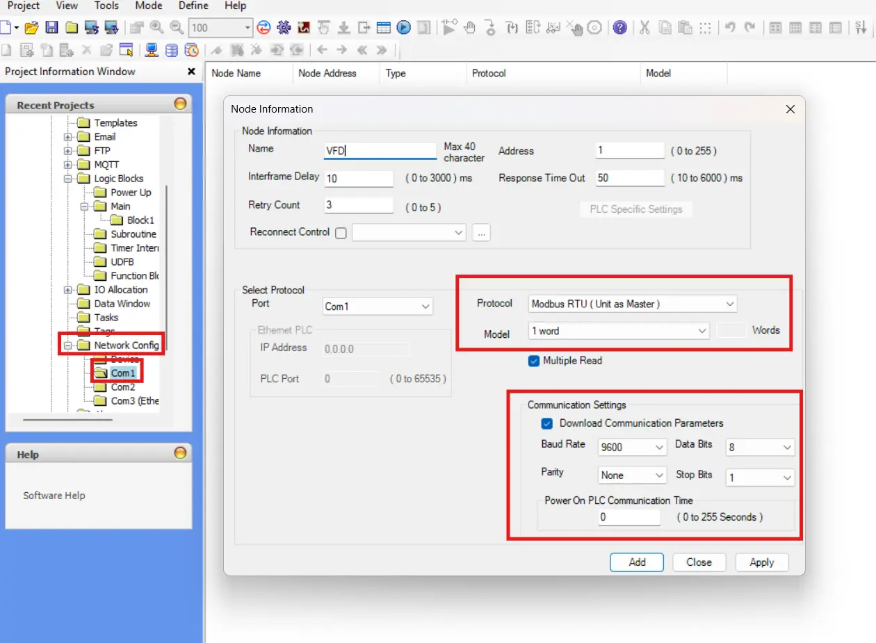
Configure our Modbus Node to communicate with the VFD
Then from here, we’ll configure our new node as Modbus RTU (Unit as Master) and making sure to match the serial settings we set on our VFD (9600bps, no parity, 8-bit data, and 1 stop bit). Also be sure to
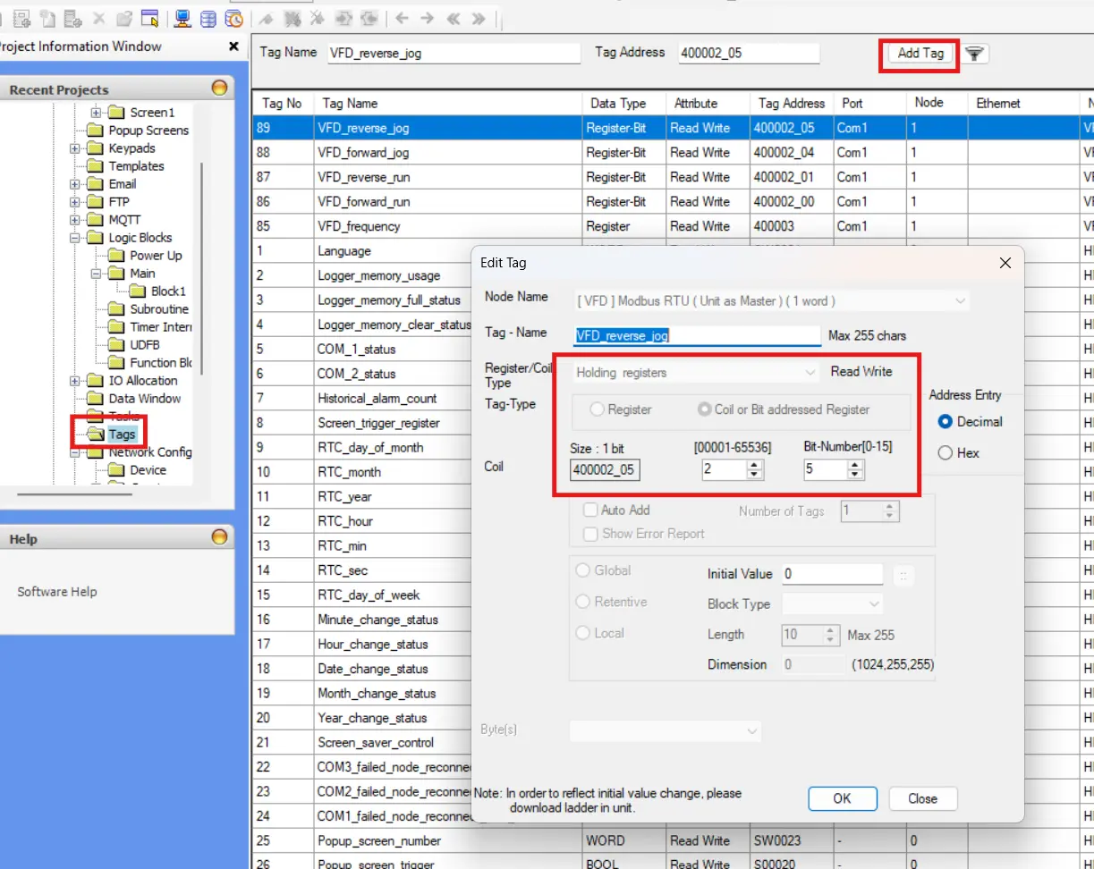
Adding Modbus Tags to MAPware-7000
Now we’ll create tags in MAPware-7000 associated with all of the Modbus addresses we’ve outlined on the VFD for controlling our motor.
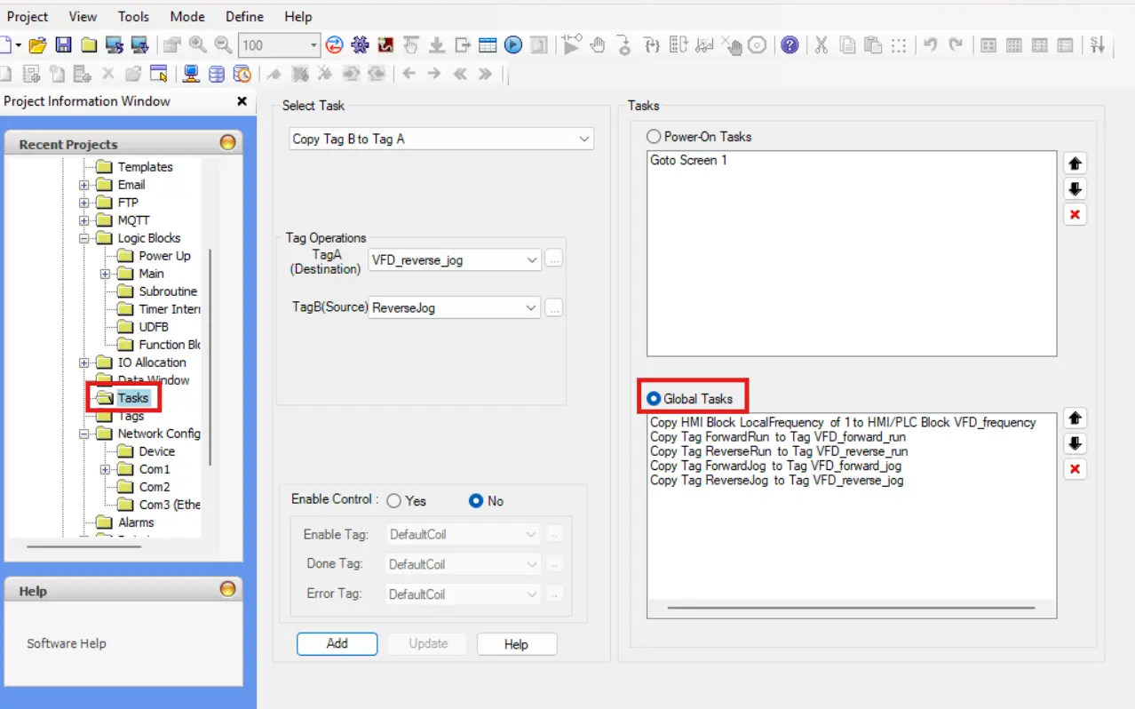
Transferring our Local data to our Modbus Tags
Next we’ll want to navigate to our “Tasks” and add Global tasks to copy the local versions of our VFD tags, to their Modbus counterparts. We’ll use the “Copy HMI Block to HMI/PLC Block” task for our frequency tag (our word tag), and we’ll use “Copy Tag B to Tag A” tasks for the boolean addresses.
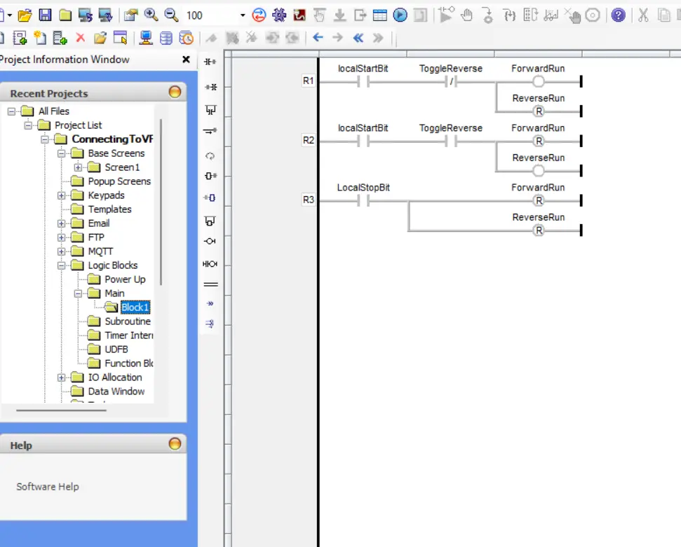
Programming Some Light Logic
Now we’ll go into our “Logic Blocks” and create a main logic block. This will mainly be to attach some functionality to our “local start” bit, “toggle reverse” bit, and our “localStop” bit, while adding some safeguards that prevent both forward and reverse from being triggered at the same time.
Download and Verification
Once the project setup is complete, it needs to be downloaded to the HMC and validated in a live environment. The following steps cover how to transfer the project and verify proper communication between the HMC and connected devices.
Download the Project to the HMC
Now that we’ve finished our HMC project, we’re ready to download it to our device.
Instructions: Download the Project to the HMC
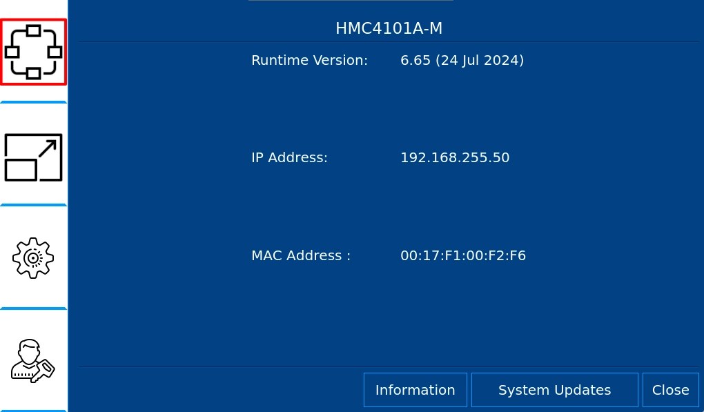
Navigating to the HMC System Settings
Now we’ll set our HMC’s IP address to something in the same subnet as our PLC. We’ll do this by pressing and holding the top-left corner of the HMC to go into the HMC system settings. Then we’ll click the “Network Settings” sidebar item.
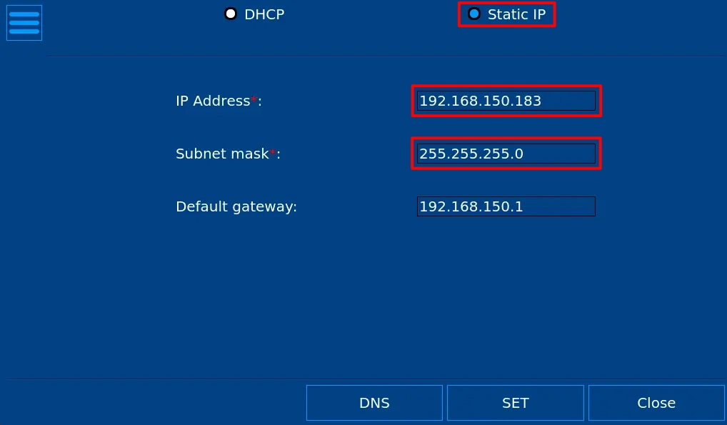
Configuring the HMC’s IP Address
In the Network settings, we’ll want to set our HMC to a static IP address, and change our HMC’s IP address and subnet mask to what we desire.
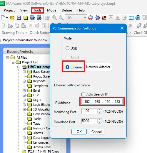
Preparing the Project for Download
Now we’ll go back into our MAPware-7000 project, navigate to “Tools > PC Communication Mode”, select “Ethernet” and change our base IP address to the IP address we just set our HMC to.
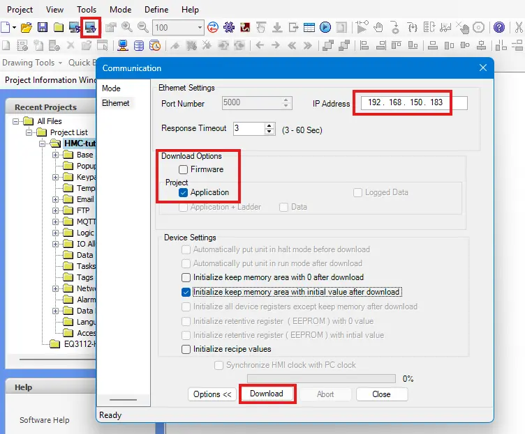
Downloading our Project
Now we’ll make sure our HMC is connected and powered on, and click the download button in MAPware-7000. After compiling the project, we’ll make sure the IP address on the download window is correct, and download our project.
Verify and Test the System
Then from here, we’ll hook up all the wiring and we should see the devices communicating with each other. Below is a video example of our HMC VFD Sample project in action.
Final Thoughts
If we return to our new conveyor belt section we want to add to our machine. Putting a VFD between our existing HMC unit and the belt itself will allow us more granular control over the conveyor belt motor. We’ll be able to implement motor soft start and soft stop to reduce motor wear, we’ll be able to fine tune the speed of the conveyor belt motor to ensure it fits in to our production line, and we’ll be able to reduce our power usage overall by including a VFD as well. Overall, using a Maple Systems HMC unit to control our VFD over Modbus will allow us to easily add any motorized machinery to our plant.
Resources & Documentation
The following guides and documentation are specific to the hardware used in this integration tutorial and will help you with setup, configuration, and programming:
- MAPware-7000
- MAPware-7000 Programming Manual
- MAPware-7000 Quickstart Guide
- Modbus Communications in MAPware-7000
- The GA500 Manual
Looking for additional learning resources? Explore our library of tutorials, example projects, and software tools to help you get the most out of your system:
Also, browse our Support Center for a complete list of installation guides, FAQs, and additional technical documentation.
About the Author
Trusted source for industrial automation & control solutions
Follow Maple Systems:
Share:


