In this tutorial, you will learn how to utilize a PID, Pulse Width Modulation (PWM), and a High-Speed Counter to control motor speed. The PID will function in a closed-loop system, controlling the PWM and using the high-speed counter (RPM) as the feedback response. The PID will control and maintain a precise rotation speed, all of which will be configured in the control software, MapleLogic.
Review these tutorials if you are unfamiliar with the functionalities of a PID, PWM and HSC in MapleLogic:
- What is a PID Controller?
- How to Control the Temperature of a Heater using a PID Loop
- What is a High Speed Counter and How is it Used with an Encoder?
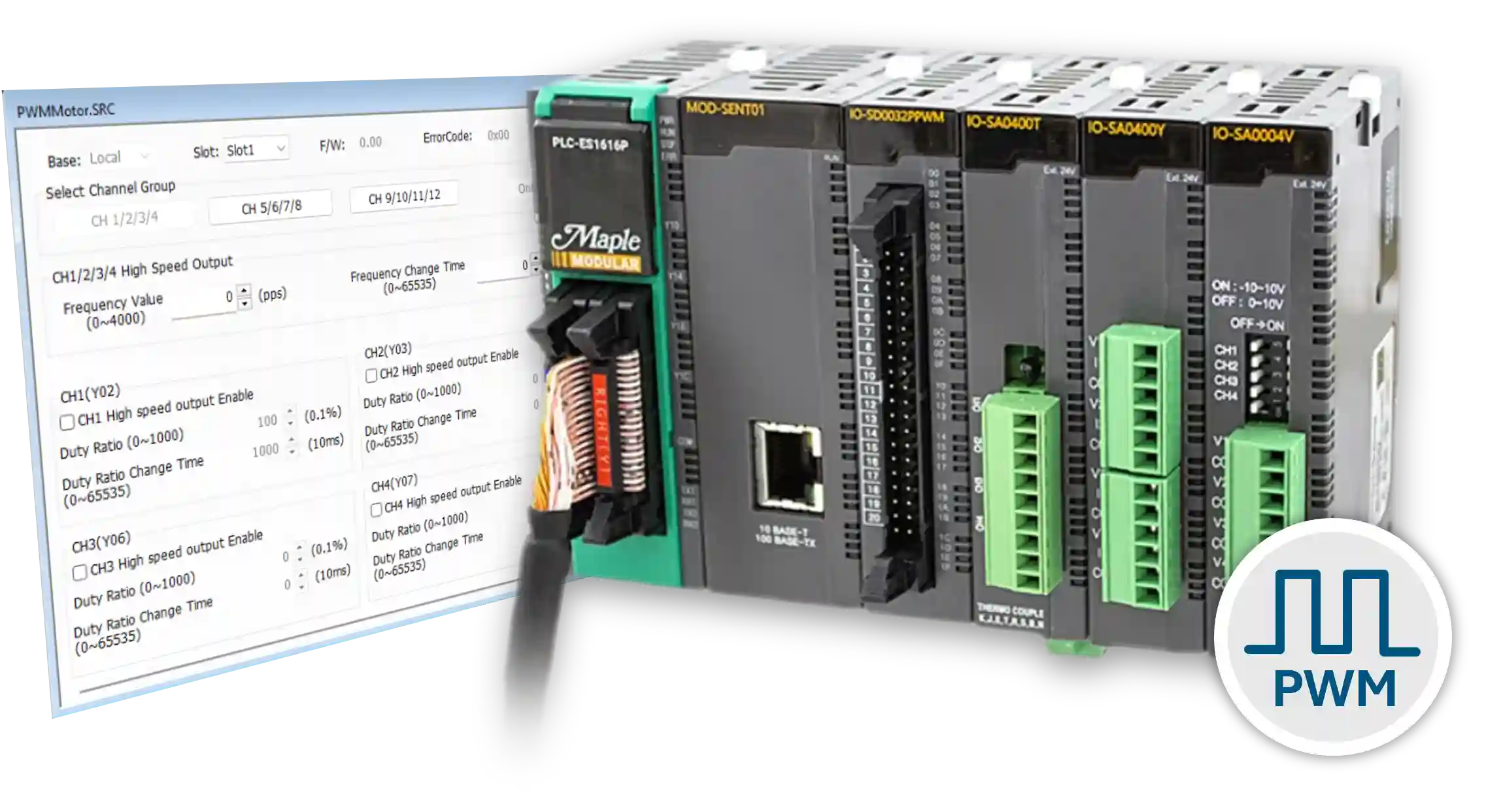
- What is Pulse Width Modulation?
- How to Control the Speed of a Motor Using Pulse Width Modulation
If you are familiar with the tutorials above, please continue on with this tutorial.
Software Required
Hardware Required
- Maple Modular PLC’S – Any Maple Modular PLC.
- PWM Module + Kit – A terminal block MUST be used with the PWM Module.
- HSC Module + Kit – A terminal block MUST be used with the HSC Module.
See the wiring and configuration below. - Two-Phase Quadrature Encoder – Encoder Model used in this example: C38HG5-100B-G24N
- 12-24V DC Motor – Motor Model used in this example: XD-3420
- DC Motor Drive Module – Drive Module used in this example: 200206_FBA
- (2) 24 VDC Power Supply (4010-0011)
Wiring Diagrams
The diagram below shows the wiring required to measure motor speed using a PID loop, Pulse Width Modulation (PWM), and a High Speed Counter. The Maple Systems PLC connects to both a PWM module and a High Speed Counter (HSC) module. Each module connects to a terminal block for field wiring. A quadrature encoder connects to the HSC module through the terminal block. The PWM module sends a PWM signal to a DC motor drive module, which controls a 24V DC motor.


This example uses a second power supply. You can use a single power supply if it provides enough current for the system.
Wiring and Circuit Design
The wiring diagram below shows how to connect a Maple Systems PLC, PWM module, terminal block, DC motor drive module, and DC motor for PWM-based motor speed control.

Important: The terminal block cannot connect directly to the DC motor. A DC motor drive module must be used between the PWM module and the motor. Connecting the motor directly to the PWM module may damage the module. Depending on your available current, you may be able to use a single power supply instead of two.
Wire the PLC, PWM Module, and DC Motor Drive
Follow these steps to wire the PWM control system safely and correctly.
Instructions: Wire the PLC, PWM Module, and DC Motor Drive
Connect the terminal block to the PWM module and PLC
Connect the ACC-TB32M terminal block to the IO-SD0032PPWM PWM module using the ACC-SBC15E terminal block cable, and connect the PWM module to the Maple PLC.
Power the Maple PLC
Wire 24V from the power supply to the 24V terminal on the Maple PLC, and wire 0V from the same power supply to the 24G terminal on the PLC.
Power the terminal block
Wire 24V from the same power supply to terminal block point A10 and jumper it to B10 to distribute 24V across the terminal block. Then wire 0V to A20 and jumper it to B20.
Select the PWM output channel
In this example, PWM Frequency Group A and Channel 4 are used. That output point corresponds to terminal B4 on the terminal block.
Wire the PWM signal to the DC motor drive module
Connect terminal B4 from the PWM output to the positive input on the DC motor drive module. Then connect 0V from terminal A20 to the negative input on the drive module.
Power the DC motor drive module
Use another power supply to provide 24V to the DC motor drive module, and connect 0V from that same power supply to the drive module negative terminal.
Connect the drive module to the motor
Connect the DC motor drive module output to the motor by wiring the positive output to the positive motor terminal and 0V to the negative motor terminal.
PWM Ladder Diagram
This example does not use the PWM Configuration GUI. Instead, ladder diagram logic in MapleLogic controls the PWM module.

Enable PWM Channel 4 in Ladder Logic
Use ladder logic and hexadecimal values to enable the correct PWM output channel on the module.
Instructions: Enable PWM Channel 4 in Ladder Logic
Review the PWM enable logic
Open the ladder diagram section that enables the PWM module output channel instead of using the PWM Configuration GUI.

Determine the hexadecimal value for Channel 4
Use a programmer calculator together with the PWM hexadecimal chart to calculate the enable value for Channel 4. In this example, Channel 4 corresponds to bit 3, which results in hexadecimal value H0008.

Enter the enable instruction in the ladder diagram
Use the instruction [TO H0001 0 H0008 1] with internal bit M00 to enable PWM output Channel 4 on the module installed in slot 1.
Calculate hexadecimal values for multiple channels if needed
If you want to enable more than one channel, combine the bit values in binary and convert them to hexadecimal. For example, Channels 4 and 1 equal H0009, while Channels 8, 4, and 1 equal H0089.


Example instruction:
—–|M00|——————-[TO H0001 0 H0008 1]—
To enable multiple channels, calculate the required hexadecimal value first. For example, Channels 4 and 1 equal H0009, while Channels 8, 4, and 1 equal H0089.

Ramp the Motor from 0% to 25% Duty Cycle
Use a timer and PWM buffer writes to bring the motor from stop to 25% duty cycle at 500 Hz.
Instructions: Ramp the Motor from 0% to 25% Duty Cycle
Enable the first speed stage
Turn on internal bit M01 to enable the first speed-control stage in rung 4.

Start the 10-second timer
Use TON TC0 100 to start a 10-second ON timer. When the timer completes, T0 turns on.
Write the ramp time, duty cycle, and frequency
Move 500 into D10 for a 5-second duty cycle ramp time, move 25 into D20 for a 25% duty cycle, and move 500 into D30 for a frequency of 500 Hz. Then write those values to the PWM module buffer memory.
Advance to the next speed stage
When T0 turns on after 10 seconds, reset M01 and set M02 so the first stage turns off and the next logic stage begins.
This stage takes 10 seconds to bring the motor from 0% to 25% duty cycle at a frequency of 500 Hz.
Ramp the Motor from 25% to 90% Duty Cycle
Use the second timed PWM stage to increase motor speed from 25% to 90% duty cycle at 500 Hz.
Instructions: Ramp the Motor from 25% to 90% Duty Cycle
Enable the second speed stage
Use internal bit M02 to enable rung 7 and begin the second speed-control stage.

Start the second 10-second timer
Use TON TC1 100 so the second speed stage runs for 10 seconds before advancing.
Write the new PWM values
Move 500 into D40 for the ramp time, 90 into D50 for the duty cycle ratio, and 500 into D60 for the frequency value, then write those values to the PWM module.
Advance to the next stage
When T1 turns on, reset M02 and set M03 to hand control to the next logic stage.
This stage takes 10 seconds to increase the motor speed from 25% to 90% duty cycle at a frequency of 500 Hz.
Reduce the Motor from 90% to 50% Duty Cycle
Use the third timed PWM stage to reduce motor speed from 90% to 50% duty cycle at 500 Hz.
Instructions: Reduce the Motor from 90% to 50% Duty Cycle
Enable the third speed stage
Use internal bit M03 to enable rung 10 and begin the third PWM stage.

Start the third 10-second timer
Use TON TC2 100 so the third speed stage runs for 10 seconds before advancing.
Write the reduced PWM values
Move 500 into D70 for the ramp time, 50 into D80 for the duty cycle ratio, and 500 into D90 for the frequency value, then write those values to the PWM module.
Advance to the final stage
When T2 turns on, reset M03 and set M04 so the final speed stage begins.
This stage takes 10 seconds to decrease the motor speed from 90% to 50% duty cycle at a frequency of 500 Hz.
Reduce the Motor from 50% to 20% Duty Cycle and Stop
Use the final timed PWM stage to lower motor speed and then turn the motor off.
Instructions: Reduce the Motor from 50% to 20% Duty Cycle and Stop
Enable the final speed stage
Use internal bit M04 to enable rung 13 and begin the final PWM speed stage.

Start the final 10-second timer
Use TON TC3 100 so the final speed stage runs for 10 seconds before shutting the motor down.
Write the final PWM values
Move 500 into D100 for the ramp time, 20 into D110 for the duty cycle ratio, and 500 into D120 for the frequency value, then write those values to the PWM module.
Turn the motor off
When T3 turns on after 10 seconds, reset M04 so the rung turns off and the motor stops.
This final stage takes 10 seconds to reduce the motor from 50% to 20% duty cycle at a frequency of 500 Hz, then turns the motor off.
PWM Online with Motor
After downloading the project, go online with the PLC and PWM module to watch the motor respond to each duty cycle stage in real time.
To see the motor speed changes more clearly, refer to the video included with this tutorial while monitoring the ladder logic online.
Monitor the PWM Logic Online
Run the PWM project online and observe how each timed logic stage changes the motor speed.
Instructions: Monitor the PWM Logic Online
Go online with the PLC
In MapleLogic, go to Online > Link + Download + Monitor to download the project and establish online communication with the PLC and PWM module.

Enable PWM Channel 4
Click the M00 bit and press Shift + Enter to turn M00 ON. This enables PWM Channel 4.
Start the first speed stage
Click the M01 bit and press Shift + Enter to turn M01 ON. This enables the TON TC0 100 instruction. The motor ramps from 0% to 25% duty cycle at 500 Hz over 5 seconds, and after 10 seconds T0 turns ON, resets M01, and sets M02.

Watch the motor increase from 25% to 90% duty cycle
When M02 turns ON, the second timer stage begins. The motor ramps from 25% to 90% duty cycle at 500 Hz over 5 seconds. After 10 seconds, T1 turns ON, resets M02, and sets M03.

Watch the motor decrease from 90% to 50% duty cycle
When M03 turns ON, the third timer stage begins. The motor ramps down from 90% to 50% duty cycle at 500 Hz over 5 seconds. After 10 seconds, T2 turns ON, resets M03, and sets M04.

Watch the motor decrease from 50% to 20% and stop
When M04 turns ON, the final timer stage begins. The motor ramps down from 50% to 20% duty cycle at 500 Hz over 5 seconds. After 10 seconds, T3 turns ON, resets M04, and the motor turns OFF.

Sample Project
This integration tutorial uses the MapleLogic sample project.
Resources & Documentation
The following guides and documentation are specific to the hardware used in this integration tutorial and will help you with setup, configuration, and programming:
- MapleLogic Programming Software
- MapleLogic User Manual
- Maple Modular User Manual
- PWM Output User Manual
- Maple Modular PLC Terminal Block & Cables
Looking for additional learning resources? Explore our library of tutorials, example projects, and software tools to help you get the most out of your system:
Also, browse our Support Center for a complete list of installation guides, FAQs, and additional technical documentation.
About the Author
Trusted source for industrial automation & control solutions
Follow Maple Systems:
Share:


