Imagine you’re in charge of an industrial production plant, where every machine is managed by a Maple Systems Modular PLC. And let’s also say you want to add a smaller conveyor belt, or side machine next to one of the current ones. You’ll want to have PLC functionality in it, but you also want some light HMI functionality as well. Which makes the Maple Systems HMI + PLC combo unit a great fit. But how would you connect a Maple Systems PLC to a Maple Systems HMI + PLC Combo?

Software Required
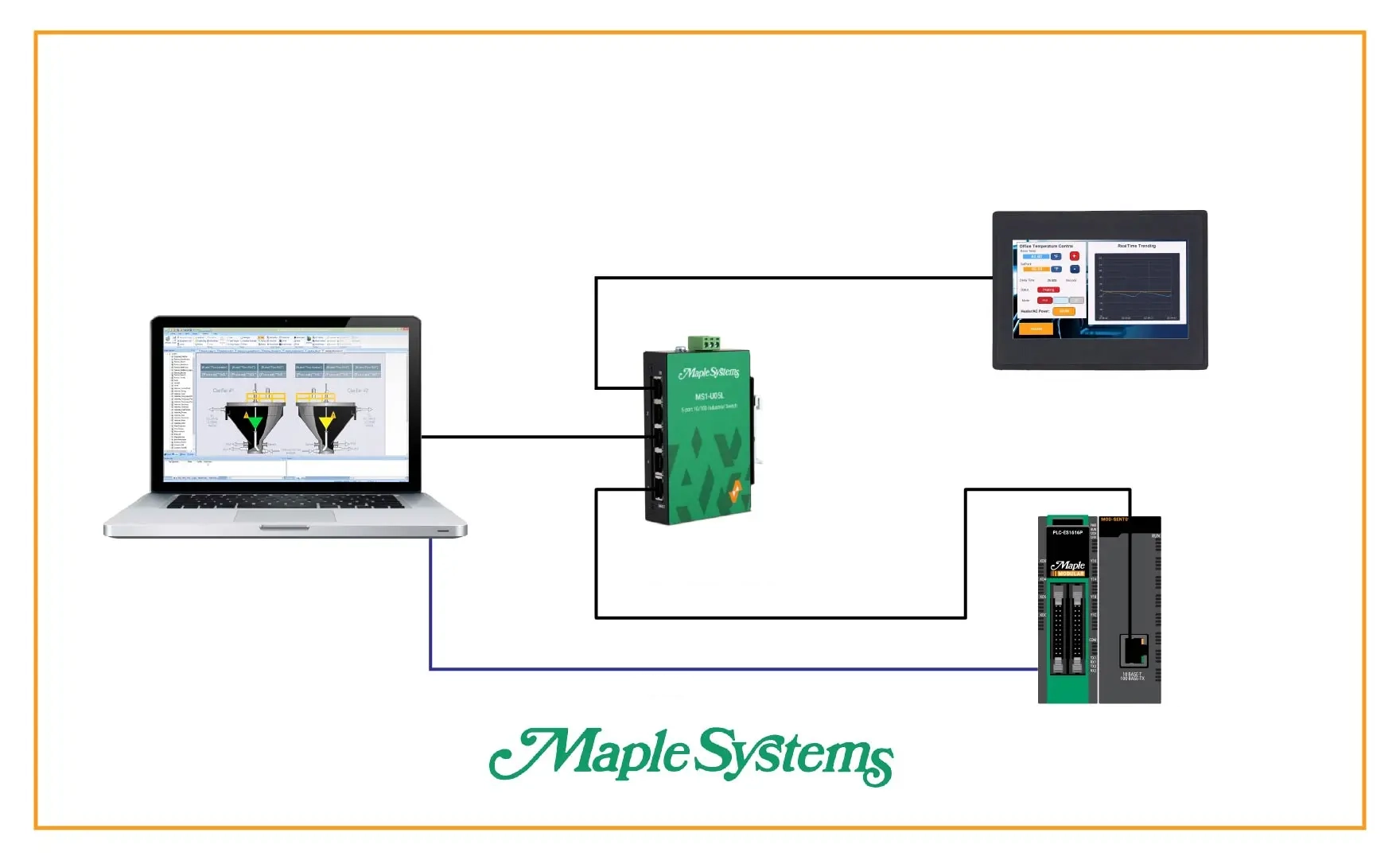
Hardware Required
- Any Maple Systems HMI + PLC Combo Unit
- Any Maple Systems Modular PLC
- A Modbus Master Module (for Ethernet connections only)
TCP/IP Connection (Ethernet)
This section explains how to establish a TCP/IP connection over Ethernet between your PLC and HMC. It covers the required settings on both sides, including network parameters, communication drivers, and protocol configuration.

PLC Configuration
First, we’ll configure our PLC as a Modbus client (master)
Instructions: PLC Configuration
Initializing a new Project
Open up a new project in MapleLogic, select modular ES as the PLC type, and name your project.

Configuring the PLC’s IP address
Open up the PLC parameters and go to the “Ethernet” tab, then change your PLC’s IP address to what you’d like. Be sure to take note of this IP address for when we configure the HMI + PLC side. Hit “OK” and save your new IP address.

Create a base project
Next, you’ll want to create a new main scan program in MapleLogic. The PLC project won’t compile or download properly if there isn’t a main scan program.

Configuring the PLC as a Modbus Master
Now we’ll create another PLC program, but set it to the “MODBUS/TCP MASTER” under the “Communication Configuration” section.

Setting the Slave IP address
Now, once in this Modbus Master Program, we’ll add a new device, and point it to our HMC’s IP address.

Choose which Modbus addresses to poll from the server (slave) device
Then we’ll click the “Add” button and add Modbus tags to poll from the server (slave) device.

Connecting to the PLC
We’ll then want to make sure to connect our PLC to the computer with a mini-USB cable. We’ll also want to make sure to set MapleLogic to download via the USB cable like so

Link + Download + Monitor
Next, you’ll want to press the “Link + Download + Monitor” button and accept all the prompts.

HMC Configuration
Then we’ll configure our HMC as a Modbus server (slave)
Instructions: HMC Configuration
Create a new MAPware-7000 project
To start, we’ll make a new MAPware-7000 project, name it, and select our HMC model.

Build out our Project
Then we’ll want to fill out our HMC project with all of the functionality we need on it.

Assign Tags to Modbus Addresses
Now that we have our project mapped out, we can set some of our MAPware-7000 tags to Modbus addresses. We’ll do this by navigating to the “Tags” database and filling an address into the “Ethernet” column of our project tags that we want to transmit to our PLC.

Navigating to the System Settings on the HMC
Now we’ll set our HMC’s IP address to something in the same subnet as our PLC. We’ll do this by pressing and holding the top-left corner of the HMC to go into the HMC system settings. Then we’ll click the “Network Settings” sidebar item.

Configuring the HMC’s IP Address
In the Network settings, we’ll want to set our HMC to a static IP address, and change our HMC’s IP address and subnet mask to what we desire.

Preparing the Project for Download
Now we’ll go back into our MAPware-7000 project, navigate to “Tools > PC Communication Mode”, select “Ethernet” and change our base IP address to the IP address we just set our HMC to.

Downloading our Project
Now we’ll make sure our HMC is connected and powered on, and click the download button in MAPware-7000. After compiling the project, we’ll make sure the IP address on the download window is correct, and download our project.

RTU Connection (Serial)
This section outlines how to configure a serial RTU connection between your PLC and HMC. It covers RS-232 wiring, configuring communication parameters, setting the Modbus Slave ID on the PLC, and matching those settings on the HMC to ensure reliable serial communication.
Note, the Modbus master module is not required to configure a Maple PLC as a Modbus master over a serial connection.

PLC Configuration
As before, we’ll start with the differences in configuring our PLC as an RTU Modbus Master
Instructions: PLC Configuration
Create a New Project
On the MapleLogic side, we can create a project with either a Maple Modular PLC or a Maple Micro PLC.
Add a Modbus/RTU Master
Now we’ll add a base scan like before, and add a “Modbus/RTU Master” program as well.

Configure the Modbus/RTU Master
We’ll specify the COM port of our Modbus Master (COM 1 for RS-232), and like before, we’ll hit the “Add” button and configure which addresses our PLC will poll from the server (slave) device.

Configure the Modbus COM port
Now we’ll go into the PLC Parameters of our project, and navigate to the “Ch 1” tab. We’ll want to ensure that our serial settings match the HMC serial settings.

Configure the Slave ID
Next, we’ll go into the “Modbus” tab and make sure the “Slave ID” matches the “Address” number on our HMC project Serial configuration.

HMC Configuration
Now we’ll discuss the HMC side of our connection, and configure an RS-232 Serial connection.
Instructions: HMC Configuration
Wiring the HMI + PLC
To start, we’ll want to attach our RS-232 wires to the proper terminal slots on our HMC’s COM 1 port.

Adding a New Serial Connection
Much like the Ethernet Node, we’ll go to “Network Configuration > Com1” page, and right-click the page to add a new device connection.

Configure a Serial Modbus Driver in MAPware-7000
We’ll then set the new driver we’re adding as a Modbus RTU (Unit as Slave) driver. Also, be sure to note the Serial Communication settings for when we’re configuring the PLC side of the connection.

Assign tags to Modbus Addresses
In a very similar way to the Ethernet method, we’ll now navigate to our Tag database, and assign Modbus registers to our project tags, but using the “Com 1” column instead.

From here, we’ll download our projects to our devices the same way as before, and our PLC and HMC will be able to communicate with each other.
Final Thoughts
By connecting a Maple Systems HMI + PLC Combo unit to your existing Maple Systems PLC infrastructure through Modbus communication, you can quickly expand your system without redesigning your entire control architecture. The HMC unit not only provides additional PLC logic for new equipment, but also adds local HMI functionality for monitoring, trending, and visualizing process data. This makes it an efficient solution for expanding production lines while maintaining centralized control and clear visibility into your operations.
Resources & Documentation
The following guides and documentation are specific to the hardware used in this integration tutorial and will help you with setup, configuration, and programming:
- MapleLogic (8.21.29)
- MapleLogic User Manual
- Maple Micro User Manual
- Maple Modular User Manual
- MAPware-7000
- MAPware-7000 Programming Manual
- MAPware-7000 Quickstart Guide
- Modbus Communications in MAPware-7000
Looking for additional learning resources? Explore our library of tutorials, example projects, and software tools to help you get the most out of your system:
Also, browse our Support Center for a complete list of installation guides, FAQs, and additional technical documentation.
About the Author
Trusted source for industrial automation & control solutions
Follow Maple Systems:
Share:


