In this tutorial, you will learn what Pulse Width Modulation (PWM) is, how it is used in industrial applications, and how to configure PWM in MapleLogic.
What is Pulse Width Modulation (PWM)
Pulse Width Modulation (PWM) controls the average power delivered to a load by changing how long a signal stays on during each cycle. PWM uses a fixed-frequency signal and switches it on and off at different intervals to create pulses of different widths.
By changing pulse width, PWM can control how much power a device receives without changing the supply voltage itself.
PWM Duty Cycle
The duty cycle shows how long a PWM signal stays in the on state during one full cycle. It compares the on-time to the total period of the signal and is usually expressed as a percentage.
A higher duty cycle delivers more power because the signal stays on longer. A lower duty cycle delivers less power because the signal stays on for less time.
Because of this, the duty cycle directly affects the average voltage or current delivered to a device and changes how that device behaves.

- A zero percent duty cycle in the context of Pulse Width Modulation (PWM) means that the signal is always in the “off” state, and there is no time during the period when the signal is in the “on” state.
- A 50 percent duty cycle in pulse width modulation (PWM) means that the signal is on for half of the total period. This implies an equal amount of time in the “on” state and the “off” state.
- A 75 percent duty cycle in the context of Pulse Width Modulation (PWM) means that the signal is on for 75 percent of the total period.
- A 100 percent duty cycle in pulse width modulation (PWM) means that the signal is on continuously throughout the entire period, and there is no “off” state.
A good example of using the duty cycle for PWM is dimming an LED light. A PWM turns the power on and off, and the perceived output is changed by varying the duty cycle.
It is how the signal is turned on versus turned off.

Above is an example of a 10V LED light.
- 0% Duty Cycle is 0V
- 25% is 2.5V
- 50% is 5V
- 75% is 7.5V
- 100% is 10V
The LED would be dim at a lower duty cycle and brighter the higher the duty cycle gets, 100% being the brightest.
PWM Frequency
Pulse Width Modulation (PWM) frequency refers to the rate at which the PWM signal repeats its cycle, measured in Hertz (Hz). It represents how quickly the signal oscillates between the “on” and “off” states.

For LED light dimming, PWM frequencies are often in the kilohertz range, typically above 1 khz.
An example of something that requires 100 Hz to several kilohertz would be a DC motor or three phase AC motors. For motors, higher PWM frequencies generally offer smoother control and quieter operation.
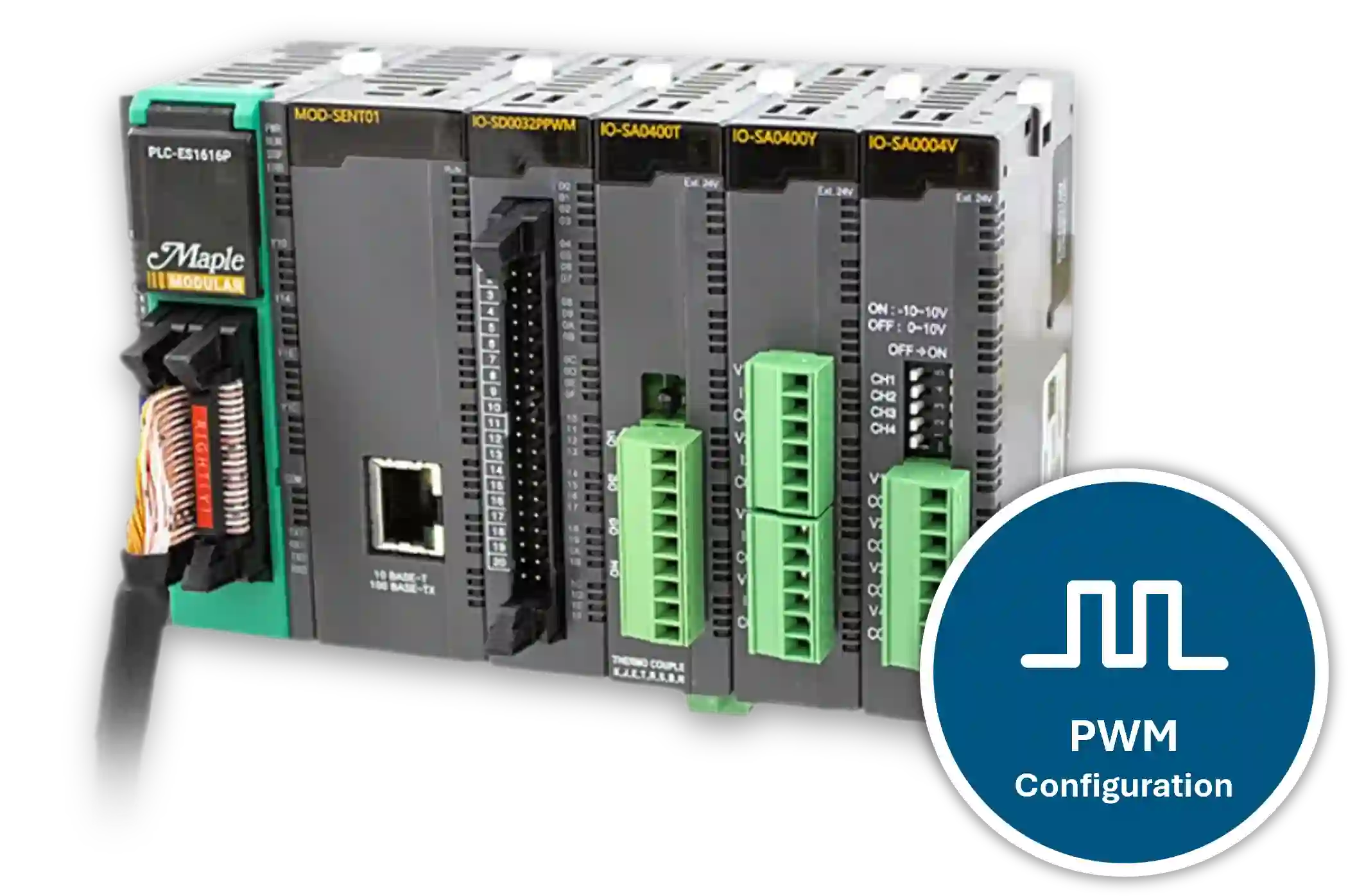
PWM Configuration in MapleLogic
Use the PWM Configuration window in MapleLogic to set up fixed PWM output values for a Maple Modular PLC.
Instructions: PWM Configuration in MapleLogic
Create a PWM program
Create a project using a Maple Modular PLC. In the Program area, right-click New Program, select PWM for PLC-ES, and click OK.

Open the PWM Configuration window
After creating the PWM program, the PWM Configuration window will open. Use this window when your PWM settings are intended to remain constant without automation.

Select the module slot
Choose the slot number for the PWM module based on where it is installed in the I/O chassis.
Choose the channel group
Select the channel group you want to configure. The PWM module has 12 total outputs grouped as channels 1-4, 5-8, and 9-12.
Enable online editing if needed
Use Online Edit to apply configuration changes and save them to the PLC while you are online.
Set frequency value and change time
Configure the PWM Frequency Value and Frequency Change Time for the selected channel group. The PWM module supports a maximum frequency of 4,000 Hz.
Enable the output channel
Check the high-speed output channel you want to use. Each PWM channel can be configured individually.
Set duty ratio and change time
Configure the Duty Ratio according to the required duty cycle and set the Duty Ratio Change Time. The PWM module supports a maximum duty cycle of 100%.
Write the PWM settings to the PLC
After configuring all settings, click Write to apply the PWM configuration to the PLC.
Initialize the configuration if needed
Click Initialize to reset all settings in the PWM Configuration window.
Review the application example
The example below shows PWM settings that can be used to control the speed of a 24V DC motor. At 1000 Hz, the motor can ramp from 0% to 100% duty cycle over 10 seconds.

PWM Module Buffer Memory
Besides the PWM Configuration window, you can also use PWM Module Buffer Memory to automate PWM control in ladder logic.
Buffer memory lets you turn bits on and off to control PWM channels, frequency, duty cycle, frequency ramp time, and duty cycle ramp time. This approach works well when your application needs full automation instead of fixed PWM settings.
For a detailed example, refer to How to Control the Speed of a Motor Using Pulse Width Modulation.
You can find the PWM Buffer Memory reference in the MapleLogic Help Files under PLC-ES > PWM Module > Buffer Memory.

Resources & Documentation
The following guides and documentation are specific to the hardware used in this integration tutorial and will help you with setup, configuration, and programming:
- MapleLogic Programming Software
- MapleLogic User Manual
- Maple Modular User Manual
- PWM Output User Manual
- Maple Modular PLC Terminal Block & Cables
Looking for additional learning resources? Explore our library of tutorials, example projects, and software tools to help you get the most out of your system:
Also, browse our Support Center for a complete list of installation guides, FAQs, and additional technical documentation.
About the Author
Trusted source for industrial automation & control solutions
Follow Maple Systems:
Share:


