Imagine a manufacturing system with sensors and actuators across multiple production line sections. In a bottling system, devices include photoelectric sensors, motors, limit switches, and pneumatic valves. These operate at stations like feeding, filling, capping, labeling, and packaging.
Traditionally, all wiring runs back to a central control cabinet. With Maple Systems Remote I/O modules, you can install modules near each machine section and connect them to a central controller, such as an S7-1200 PLC.

In this setup, remote I/O modules sit far from the PLC. They connect to the communication module using a high-speed data cable. This approach reduces extensive wiring in large facilities with distributed field devices. The communication module sends all process data to the PLC through a single cable.
Software Required
- EasyRemote IO (Required software for any Maple Systems Remote I/O)
- TIA Portal v19 (Required Software for the S7-1200 PLC)
Hardware Required
- Any Maple Systems Remote I/O Coupler can be used. (iR-ETN40R used in this example, which is a remote coupler and remote I/O combo)
- Siemens PLC (Simatic S7-1200 is used in this example)
Network Diagram

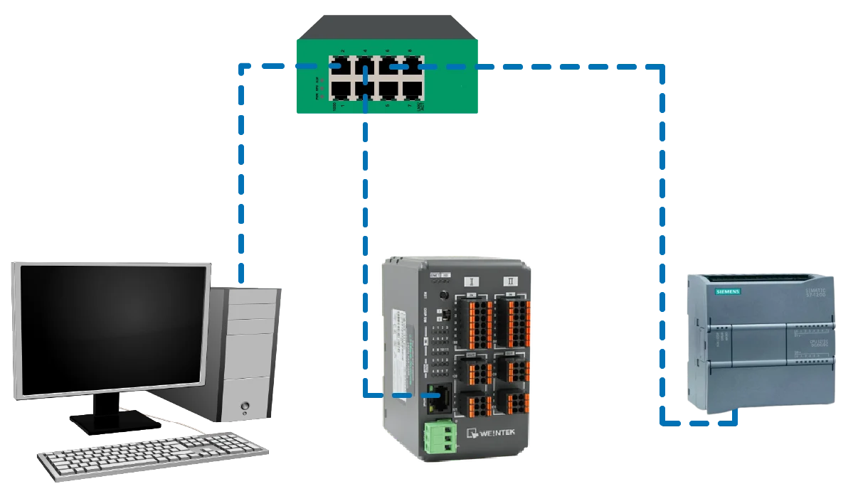
The diagram above illustrates the network setup in this article. At the top of the diagram, a network switch serves as the central communication hub, linking all devices through Ethernet connections.
On the left side, a PC is connected to the network (192.168.255.75) and is typically used just for programming, monitoring, or configuring the control system using EasyRemote IO and the S7-1200 PLC TIA Portal (Totally Integrated Automation Portal).
In the middle, a remote I/O module (such as the iR-ETN40R) is shown and is also on the same subnet (192.168.255.57). The Remote I/O communicates over Modbus TCP/IP Protocol with a Siemens S7-1200 PLC (192.168.255.28), which acts as the main controller that processes the inputs and controls the outputs of the system.
Remote I/O Configuration
Here you will learn how to add an iR-ETN40R Network Coupler to a new EasyRemote IO project and start monitoring it to view its online status and values.
Starting a new EasyRemote IO Project
Follow the step-by-step guide in configuring an iR-ETN40R Remote I/O Coupler in the EasyRemote IO software.
Instructions: Starting a new EasyRemote IO Project
Adding Network Coupler
– Click the Network Coupler icon
Enter IP Address
- Select the iR-ETN40R for this example
- Enter the IP address of the Network Coupler
- Click OK
The default IP address is 192.168.0.212
Automatic Scan
– Instead of entering the IP address, Automatic Scan can be used
Press Scan
– Click Scan
Scanning Complete
- The Network Coupler will populate along with the IP address
- A pop up indicating that the scanning is complete
- Click OK

Start Monitoring
- The Network Coupler is added into the project
- Click Start Monitoring to view online values

Monitor Started
- The Network Coupler is highlighted green when monitoring has started
- Monitor is started is displayed in the Log Message

PLC Configuration
Below is a step-by-step procedure to configure a Siemens S7-1200 PLC.
Configuring a Siemens PLC in TIA Portal
Follow this step-by-step guide in configuring an S7-1200 PLC in the TIA Portal
Instructions: Configuring a Siemens PLC in TIA Portal
Launch TIA Portal and Create a Project
- Open TIA Portal software.
- In Portal View, select Create new project.
- Enter: Project name, Storage location
This creates the project environment where all hardware configuration and programming will occur.
Add the S7-1200 PLC to the Project
- In Portal View, select Devices and Networks
- Navigate to: Controllers > SIMATIC S7-1200
- Choose the correct CPU model (1212C for this example)
- Select the firmware version matching the physical PLC.
- Click Add
The PLC will appear in the Device View hardware configuration
Device Configuration
- Double click Device Configuration
- Here you can see that the PLC was added to the Rack_0
- Save the project

PLC Logic Build
Below you will learn how to create and test a basic PLC control program using a Siemens S7-1200 in TIA Portal. The example will be a simple start/stop for a motor.
Siemens PLC Ladder Logic
Follow this step-by-step guide in building ladder diagram logic in SIMATIC STEP 7 basic (TIA Portal)
Instructions: Siemens PLC Ladder Logic
Adding Ladder Diagram Logic Block
- Add a new block
- Name it Stop_Start for this example
- Select Function
- Language: LAD (Ladder Diagram) for this example
- Click OK to add it as a Program Block

Create PLC Tags
- Type the name of the tags under Name (Stop, Start, Motor)
- Change the data types to Bool

Editing PLC Addresses
- Address: Stop: 0.0, Start: 0.1, Motor: 0.2
- Change the operand identifier for Motor to Q, which is output
Think of it like this:
The first number (
0) = which byte/word you’re looking atThe second number (
0) = which bit inside that byteSo:
0.0> byte 0, bit 0 (the very first bit)0.1> byte 0, bit 10.2> byte 0, bit 2
Add Logic Blocks to a Rung
- Add two normally open contacts to the rung
- Simply drag the block to the rung

Adding Tags to Logic Blocks
- Add a tag to the logic block
- Click the question mark and drop down menu and select the tag

Tags added to Logic
– Add the remaining tags to the logic blockFor more details on adding logic blocks to the rung, refer to the

Add Function to Main Logic
- Now you will need to add the Stop_Start Function to the Main [OB1] program block
- Open the Main [OB1] program block and click and drag the Stop_Start function onto the rung. This will add it.
In simple terms, the PLC only runs the logic that is inside the main program cycle.
In TIA Portal, the Main Block (usually OB1) is what the PLC actually executes every scan.
What happens if you don’t add the FB to OB1?
The PLC:
1. Runs OB1
2. Executes only the instructions inside OB1
3. Ignores any FBs or FCs that are not called
So even though the FB exists in the project, the PLC never runs it, so you won’t see its logic operating when online.

Function Added to Main Block
– The FB is now placed in the Main scan
Modbus TCP Configuration in TIA Portal and EasyRemote IO
Below shows how to configure an S7-1200 PLC as a Modbus TCP client (master) in TIA Portal to communicate with a Maple Systems iR-ETN40R Remote I/O as a Modbus TCP server (slave).
Modbus TCP Client Instructions in TIA Portal
Follow this step-by-step guide in getting started with configuring the S7-1200 PLC as a modbus client (master) to communicate with a Maple Systems Remote I/O (iR-ETN40R) as the modbus server (slave)
Instructions: Modbus TCP Client Instructions in TIA Portal
PLC IP Address
- Right click on the ethernet port on the Siemens PLC GUI
- Navigate to the Ethernet Address tab
- Enter the IP address and Subnet mask of the S7-1200 PLC
The PLC and Remote will need to be on the same network and share the same subnet.
Add Modbus Configuration Program Block
- Add a new block
- Select Data Block
- Name it MBConfig
- Type: Global DB
- Click OK

Add Modbus TCP (Client) Instruction to Main Block
- Select the Main [OB1] Block
- Drop down the Communications Instruction
- Select Others folder
- Select MODBUS TCP
- Drag the MB_CLIENT Instruction intot the Main Block on the rung after the normally closed contact

Name the Call Option
- Call options with pop up when the instruction is placed in the main block
- Name it MB_CLIENT_DB (Modbus Client Data Block)
- Click OK

Assign Tags to the Instruction
- Now add the tags to the instruction
REQ= starts a Modbus requestDISCONNECT= tells the block to close the connectionMB_MODE= tells it what Modbus function to useMB_DATA_ADDR= starting Modbus address in the serverMB_DATA_LEN= how many items to read or writeMB_DATA_PTR= where the PLC stores the data or gets data to sendCONNECT= server connection infoDONE= request finished OKBUSY= still workingERROR= request failedSTATUS= error/status codeThink of
MB_CLIENTlike this:CONNECT = who to talk to
MB_MODE = what action to do
MB_DATA_ADDR = where in the server to start
MB_DATA_LEN = how much data
MB_DATA_PTR = where your PLC stores it
REQ = go do it
DONE / ERROR / STATUS = tell me what happened
To see more details on this instruction and its usage please refer to the Simatic S7 S7-1200 Programmable Control Manual – Communication processor and Modbus TCP

Remote I/O Modbus Parameters
– Check to make sure the modbus parameters is set to Modbus TCP in EasyRemote IO
Remote I/O Address Map
- Select the Address Map
- Built-in “I” (the channels being used)
- Look at Channels 0-2 modbus addresses
Channel 0 is 0x_0, Channel 1 is 0x_1 and Channel 2 is 0x_2
Think of it as:
address group = digital bit area
0= the first bitSo
0x_0is basically the first digital point.In TIA Portal
If you want to communicate with that bit through
MB_CLIENT, you would typically set:MB_DATA_ADDR := 0MB_DATA_LEN := 1MB_MODEbased on what it is:read discrete input for an input
read coil / write coil for an output
MB_DATA_PTRpoints to where the result will be stored in your PLC memory
Modbus Client Instruction with Tags
Here is what the instruction will look like with the tags assignedAgain for more details use the Simatic S7 S7-1200 Programmable Control Manual
Below will be the steps in downloading the project and establishing online connection with the PLC.
Compile and Download Project to the S7-1200 PLC
Follow this step-by-step guide in compiling and downloading a PLC project in TIA Portal to the S7-1200 PLC
Instructions: Compile and Download Project to the S7-1200 PLC
Compile the PLC Project for Hardware
- Right click on PLC 1 [CPU 1212C…]
- Select Compile
- Select Hardware (rebuild all)
- Hardware will be compiled
Compiling the hardware configuration makes sure:
- The PLC knows what modules are installed
- I/O addresses are assigned correctly
- The rack and network setup match the real PLC
For example, it tells the PLC things like:
Slot 1 = CPU
Slot 2 = digital input module
Slot 3 = digital output module

Compile the PLC Project for Software
- Right click again on PLC 1 [CPU 1212C…]
- Select Compile
- Select Software (rebuild all)
Compiling the software checks and prepares your program:
- Checks for errors in logic
- Makes sure tags and addresses are correct
- Converts ladder/FBD into PLC machine code
Without compiling, the PLC may not accept the program or it might contain errors.

Project Compiled
– Compiling finished with no errors or warnings
Download to PLC
- Right click again on PLC 1 [CPU 1212C…]
- Select Download to device
- Select Hardware and software (only changes)

Download Preview
- The Load Preview window will pop up
- Click Load to begin downloading

Download Completed
- a Load results window will pop up indicating that Downloading to device completed without error
- Click Finish

Save Project and Go Online
- Save the project
- Click Go online

PLC Online
– In the Project tree, the PLC, Program Blocks, PLC tags and Local modules have a green check mark or circle indicating that everything was downloaded to the PLC successfully
Monitor the PLC Project
- The last step is to monitor the online project
- Select the Monitoring on/off button to monitor the PLC values in the logic block

You are now ready to apply your Maple Systems Remote I/O and Siemens S7-1200 PLC in real-world applications. By combining the functionality of the Siemens PLC with the Maple Systems Remote I/O, you are prepared to design practical automation solutions and implement them in real operating environments.
Recap
First, we explored how a Siemens S7-1200 PLC communicates with Maple Systems Remote I/O in a distributed control system. Instead of wiring all devices to one cabinet, you can connect sensors and actuators to nearby remote I/O modules. Then, these modules send data to the PLC using Modbus TCP/IP over Ethernet. Next, we configured the PLC in TIA Portal, created ladder logic, and set up PLC tags. After that, we downloaded and monitored the program to verify operation. Finally, we configured and monitored the remote I/O using EasyRemote IO software.
Next Steps
Next, connect real field devices to the remote I/O and control them with the PLC program.
For example, wire a photoelectric sensor to a remote input and a motor or pneumatic valve to a remote output. Then, modify the ladder logic so the PLC reads the sensor through the Maple Systems Remote I/O. When conditions are met, the PLC activates the actuator. This setup demonstrates real input/output communication over Modbus TCP/IP between the S7-1200 and remote I/O. It also allows you to test troubleshooting, monitor values, and expand the automation system.
Resources & Documentation
The following guides and documentation are specific to the hardware used in this integration tutorial and will help you with setup, configuration, and programming:
- EasyRemote IO User Guide
- Remote I/O Datasheet
- Simatic S7 S7-1200 Programmable Control Manual
- Simatic TIA Portal Step 7 Basic V10.5 Getting Started Guide
Looking for additional learning resources? Explore our library of tutorials, example projects, and software tools to help you get the most out of your system:
Also, browse our Support Center for a complete list of installation guides, FAQs, and additional technical documentation.
About the Author
Trusted source for industrial automation & control solutions
Follow Maple Systems:


