Imagine a packaging line that runs multiple products on the same machine. As each box reaches the labeling station, a barcode scanner reads the printed label and sends the scanned code to the HMI.
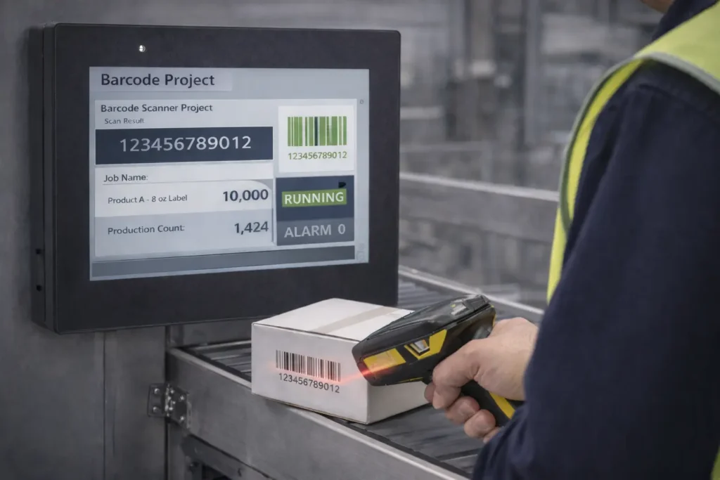
The HMI displays the scanned value on the screen and makes it available to the control system for use by the active production job. The HMI also shows the current job information, production count, and any related system messages so operators can see what is happening at the labeling station in real time. This gives operators immediate visibility at the machine and supports automatic traceability without manual data entry.
The barcode scanner can connect to the HMI directly or through the control network using Ethernet protocols such as Modbus TCP or EtherNet/IP, or through a supported USB or serial interface. The HMI’s role is to present the scanned code and job status in a clear, operator-friendly interface.
Software Required
Hardware Required
- Any Maple Systems HMI can be used. (cMT2058XH used in this example)
- Barcode Scanner
Network Diagram

The diagram illustrates a simple network and barcode-scanner setup for an HMI system.
A PC and a 4.3″ HMI connect by Ethernet to the same network switch at the top of the diagram. The PC uses IP address 192.168.255.58 and the HMI uses IP address 192.168.255.57, placing both devices on the same subnet so they can communicate directly over the network.
The barcode scanner connects directly to the HMI through a USB cable. In this configuration, the HMI receives barcode data locally over USB, while the PC communicates with the HMI over Ethernet for tasks such as project download, monitoring, and configuration.
*Note – You only need the PC to initally download the project to the HMI.
Barcode Scanner Configuration on an HMI
Now we are going to configure the barcode scanner device in EBPro so that it can communicate with the HMI.
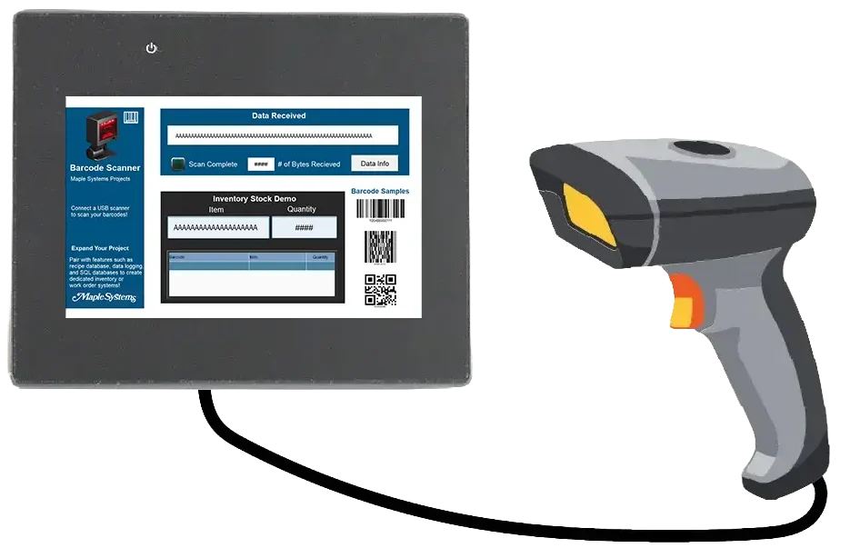
Below is the sample project that will be covered in the next section.

Configuring a Barcode Scanner in EBPro
Below are steps that walk you through setting up a barcode scanner protocol driver in EBPro and different objects like ASCII, Bit Lamps, Numeric Displays, and Macros that will receive data from the barcode scanner which is connected to the HMI.
Instructions: Configuring a Barcode Scanner in EBPro
Add Barcode Scanner Protocol Driver
- Add a new device
- Select the Barcode Scanner/Keyboard device

Select USB for Connection
– In the device settings select USBIn this example choose USB, but you could also use Serial (RS-232,RS-485) or Ethernet.
Scan Complete Bit Lamp
- Add a Bit Lamp
- Open the Bit Lamp properties
- Choose Barcode Device
- Address is FLAG_0
Flag indicates the status of the data read. When reading data, FLAG 0 is set to OFF and will return to ON when it finishes reading successfully.
Number of Bytes Received
- Add a numeric display object
- Open the properties
- Choose Barcode Device
- Address is BARCODE 0
BARCODE 0 represents the number of bytes read
Add ASCII Object
- Add ASCII object
- Open the properties
- Data Format is Encoding: UTF-8(Default)
- Choose Barcode Device
- Address is BARCODE_1
This is an ASCII Display that monitors the register 32 words of data starting at register BARCODE1. The ASCII Display object properly decodes the data and displays it as text.
Add a Recipe Database
- Navigate to Data/History > Recipe Database > New
- Add Items into the Recipe Database

Add Recipe View
– Navigate to Data/History > Recipe View– When the bracode or QR code is scanned on the project screen, the item will be displayed in the Item (ASCII object) and Quantity (Numeric Display), as well as in the Recipe View table
Add ASCII for Stock Item
- Add an ASCII object
- Change the Read address to RECIPE_Item
This will display the item when the barcode is scanned
Add Numeric Display for Stock Quantity
- Add a numeric display object
- Change the read address to RECIPE_Quantity
This will display the quantity of the item that is scanned
Live Simulation
In the simulation, the barcode scanner is connected to the HMI via USB. The Barcode Scanner Connection Status bit lamp is on, indicating that the scanner is connected.
When the barcode scanner scans the barcode on the box, the decoded data is displayed in the Data Received ASCII object. The Scan Complete bit flashes green, and the Number of Bytes Received is displayed.
Recap
This tutorial explains how to use a barcode scanner with a Maple Systems HMI to verify products on a packaging line and reduce labeling errors. The HMI receives each scanned code and displays it on the screen. It then checks the code against the active job to determine a pass or fail result, trigger a reject output, and update production counts. A barcode scanner can typically connect to an HMI over Ethernet, serial (RS-232/RS-485), or USB, depending on the device and application.
In this setup, the PC and HMI communicate over Ethernet on the same network. The barcode scanner connects directly to the HMI through USB. In EBPro, you configure the scanner with standard objects such as Bit Lamps, ASCII Displays, and Numeric Displays. These objects track scan status, connection state, byte count, and the decoded barcode data in real time.
Next Steps
An optional next step is to add job and recipe validation logic so the HMI can compare each scanned barcode to the active product or job and determine a true pass or fail result.
After the system creates the result, connect it to real outputs such as a reject solenoid, a diverter, a stack light, or a buzzer through a Maple Systems PLC or remote I/O. You can then add clear on‑screen indicators for pass, fail, and scanner connection status on the Maple Systems HMI so operators receive immediate feedback.
After that, enable data logging or data transfer so the system stores each scan with a timestamp and job number. This provides basic traceability and reporting. Finally, harden the application for production by adding no‑read detection, scan timeouts, and duplicate‑scan handling. These safeguards ensure the system behaves reliably during normal and fault conditions.
Sample Project
This integration tutorial uses the EBPro Sample Project.
Resources & Documentation
The following guides and documentation are specific to the hardware used in this integration tutorial and will help you with setup, configuration, and programming:
Looking for additional learning resources? Explore our library of tutorials, example projects, and software tools to help you get the most out of your system:
Also, browse our Support Center for a complete list of installation guides, FAQs, and additional technical documentation.
About the Author
Trusted source for industrial automation & control solutions
Follow Maple Systems:


