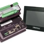
4.3" Standard HMI + PLC
$410.00
Expandable Class I Division 2, HMI+ PLC combines the ease of a graphic HMI with PLC functionality in one unit and one software. Pair this with one of our HMC3 I/O modules, to make it a customized and cost effective solution for your application. Paired with free configuration software, the HMC2043A-M product is best suited for upgrades from the HMC3000 series.
Did you know that our HMI+PLCs can communicate via Modbus to most PLCs or device, including Allen-Bradley PLCs? Visit our support center for downloadable Controller Information Sheets.
- HMI+PLC Training videos offering step by step instructions.
- US-based technical support.
Share the product:
Compare to Similar Models
Compare HMC2043A-M with 1 other product


- Support for 1 I/O Expansion Module
- IEC 61131-3 Programming Logic
- Class I, Division 2 Rated
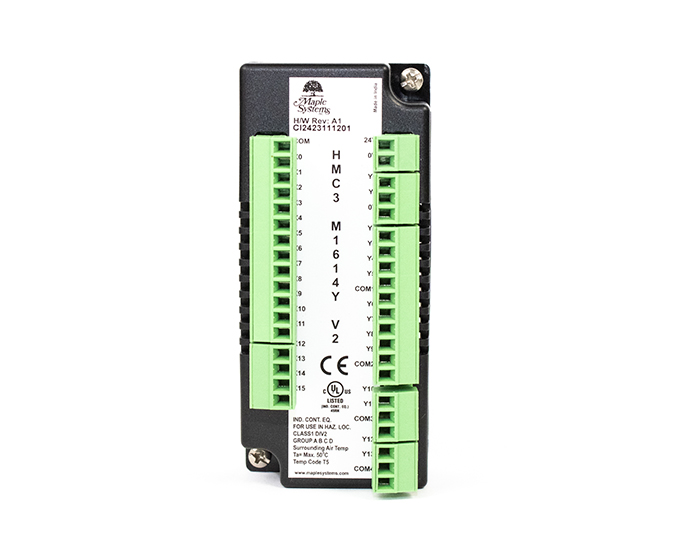
INPUT/OUTPUT
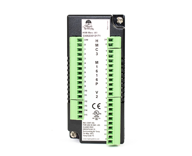
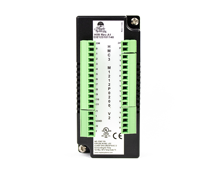
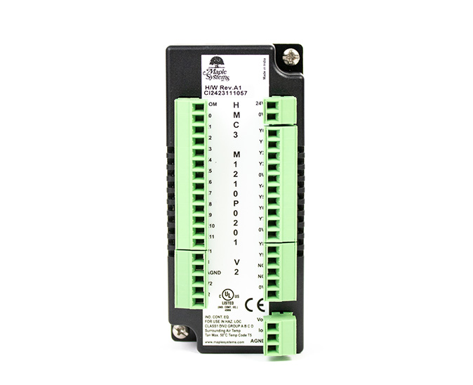
HMC3-M1212P0200-V2
$165.00
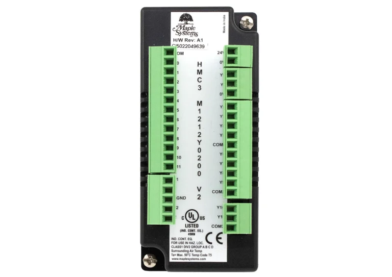
HMC3-M1212Y0200-V2
$165.00
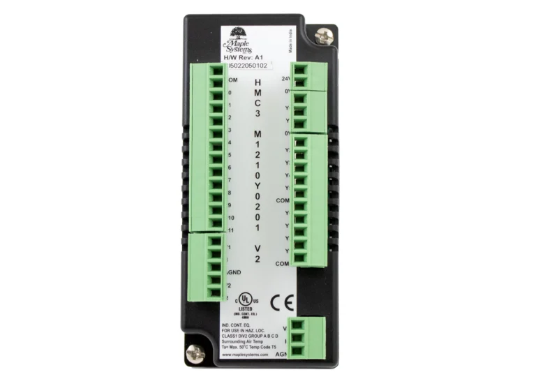
HMC3-M1210Y0201-V2
$180.00
System
| CPU | 32-bit RISC 454MHz |
| Memory (RAM) | 16 MB |
| Memory (Flash) | 16 MB |
| RTC | Built-in |
| Application Memory | 8 MB |
| Programming Software | MAPware-7000 (Latest Version) |
| PLC Ladder Memory | 2 MB |
| PLC Ladder Logic | Yes |
I/O Ports
| Ethernet/LAN | 10/100 Base-T x 1 |
| CANbus | N/A |
| Audio Output | N/A |
| SD Card Slot | SD/SDHC (32GB capacity) |
| USB Host Ports | USB 2.0 x 1 (Type A) |
| USB Client Ports | USB 2.0 x 1 (Type C) |
| Wi-Fi | N/A |
| COM Port | COM1: RS-232, COM2: RS-485 2W/4W |
| RS-485 Dual Isolation | N/A |
| I/O | Expandable |
| I/O Slots | 1 |
| Max I/O Points (Digital) | 32 |
| Max Digital In | 16 |
| Max Digital Out | 16 |
| Max I/O Points (Analog) | 5 |
| Max Analog In | 4 |
| Max Analog Out | 1 |
| Serial Ports | 1 |
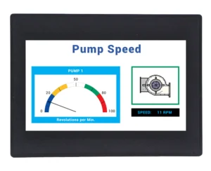
Display
| Display Size | 4.3" WQVGA |
| Resolution | 480 x 272 |
| Luminance (cd/m^2) | 400 |
| Contrast Ratio | 500:1 |
| Backlight Type | LED |
| Backlight Lifetime (hrs) | 25,000+ |
| Colors | 16.7 M |
| View Angle (H° V°) | 115/115 |
Touch Screen
| Type | TFT Resistive |
Electrical
| Input Current (Base Only) | 150 mA @ 24 VDC |
| Input Power (Base Only) | 3.6 W |
| Input Current w/ Expansion(s) | 180 mA @ 24 VDC |
| Input Power w/ Expansion(s) | 4.32 W |
| Power Isolation | N/A |
| Input Voltage | 24 VDC +20%, -15% |
Mechanical
| Vibration Endurance | 5 to 150Hz (X, Y, Z direction 3G peak) |
| Enclosure Material | Black Plastic |
| PCB Coating | N/A |
| Dimensions WxHxD | 4.72 x 3.50 x 1.26 [120mm x 89mm x 32mm] |
| Panel Cutout (inches) [mm] | 4.37 x 3.14 [111 x 80] |
| Weight | Approx. 0.44 lbs. [0.2 Kg] |
| Mounting | Panel mount |
| Shock (Operation) | 25 g acceleration for 11 ms |
Environmental
| Operating Temperature | 32~122°F [0~50°C] |
| Storage Temperature | -4° ~ 185°F (-20° ~ 85°C) |
| Relative Humidity | 10% ~ 95% (non-condensing) |
Certification
| UL Type Rating | UL Class 1 Div 2 |
| IP Rating | IP66 Compliant Front Panel |
| CE | Yes |
| UL | cULus Listed |
| Class 1 Div 2 | Yes |
| RoHS | Yes |
Unboxing an HMC2043A-M
Unbox & view accessories, attach & configure I/O Modules, download a project & view some features
Free HMI+PLC Configuration Software
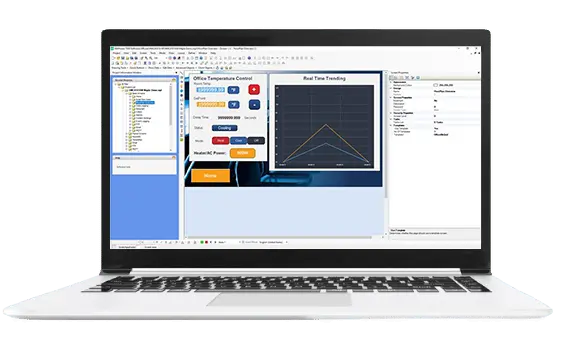
MAPware-7000 is the free configuration software used to program our HMI+PLC combo units using the IEC 61131-3 programming language. One software to program your graphics and system logic, for a complete control solution. No license or software key is needed.
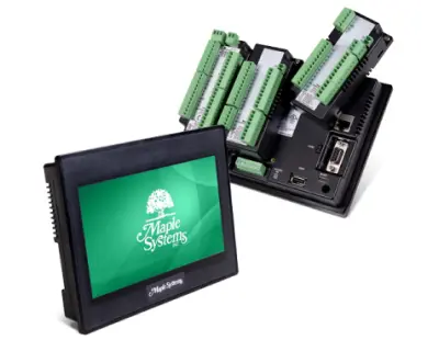
What is a Human Machine Controller (HMC)?
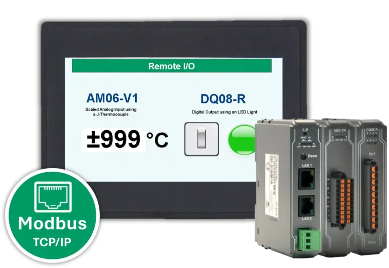
A Human Machine Controller (HMC or HMI + PLC) combines an HMI and PLC into one unit.The HMI + PLC can display visualizations on the LCD touch panel as well as run logic control internally. Pluggable I/O can be attached to the back of the unit.
Utilized worldwide in diverse applications, a Maple Systems HMI + PLC offers lower costs, saves space, and offers both Serial and Ethernet communication.
How many I/O modules can I attach to your HMI+PLC combo units?
4.3″ HMI+PLC units have one expansion slot, allowing for one I/O module.

7″ HMI+PLC units have three expansion slots, allowing for three I/O modules.

10″ HMI+PLC units have five expansion slots, allowing for five I/O modules.

What is MAPware-7000?
MAPware-7000 is the configuration software used to program our HMI+PLCs. Use just one software application to program both the screens that appear in the display as well as the logic that controls your system. Create a functional user-interface for your control system using built-in tools. In addition, the built-in I/O can be used to control and monitor your system utilizing the logic instructions integrated in the software. Program the PLC IEC1131-3 mode. The graphics program and logic program work together to provide complete control through the graphic interface.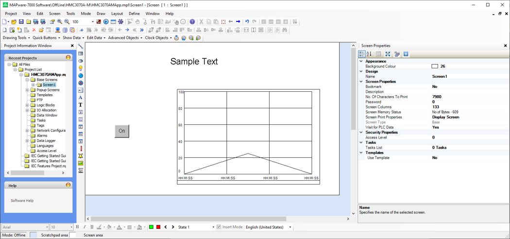
What is your standard lead time on the HMC units and their Modules?
We have large amounts of inventory and can typically ship within 1 to 2 business days! Contact our technical sales team today.
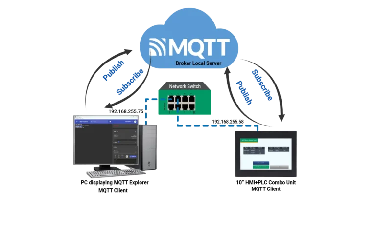
How to find the IP address of an HMI+PLC on a network
HMI+PLC (HMC)
To view the programmed Ethernet parameters of your HMC2, HMC3 or HMC7 on the network, press and hold the lower right corner of the screen while powering on.
On a HMC4 series screen, press/click and hold the top left corner of the screen for 5 seconds while the device is powered on.
Set RTC (Run Time Clock) in a HMC (MAPware7000)
To set the RTC on the screen, you can import a pop up screen from the start up project for the model of HMC that you are using.
To import the screen into your current project, select one of your base screens and go to Screen > Import screen and navigate to the start up project:
The start up projects install with MAPware7000 in the file path “C:MapleSystemsMAPware-7000Projects”.
Select the startup project file with the same model as your current project, for example, if you are using the HMC3070A-M, select project file “HMC3070AM STARTUP.mpl”
Next, select the “SetRTC” popup screen and click Import.
Add a button to open this popup screen into your project.
After downloading this project to your HMC, you will now be able to modify the RTC from your HMC screen.
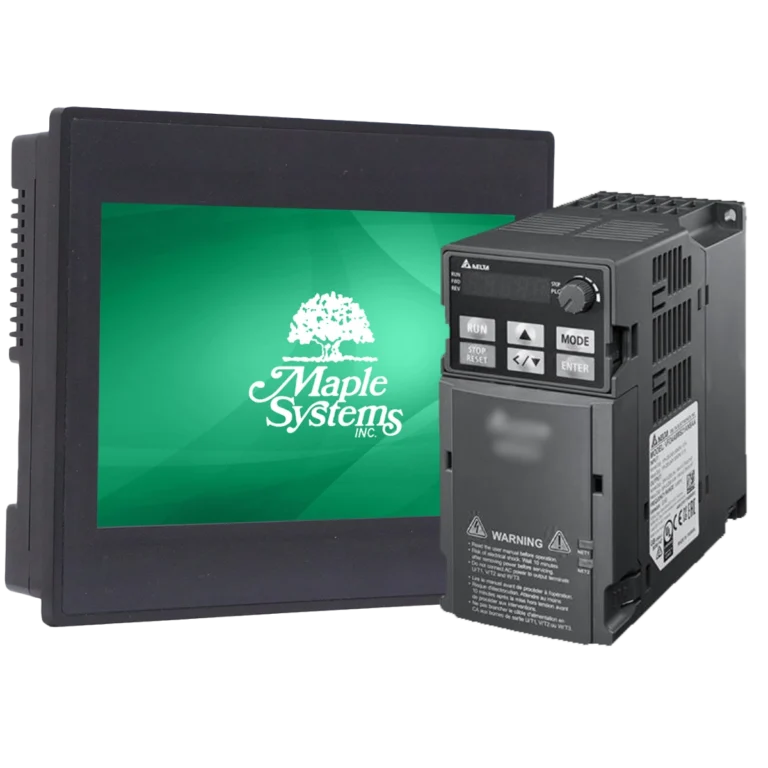
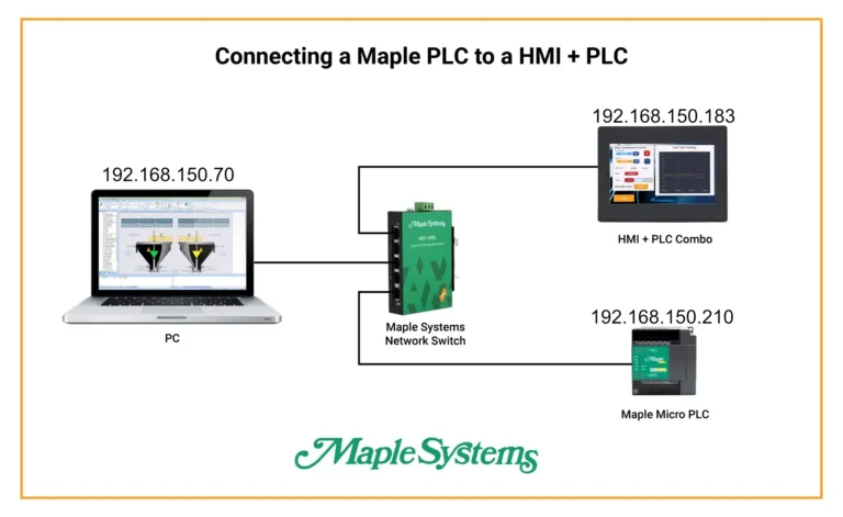
Can I pair an HMI+PLC (HMC) with a Maple Systems PLC?
Absolutely. Maple Systems PLCs can communicate with an HMI + PLC (HMC) either with or without I/O modules attached to it. A potential application would be to have the PLC installed in a remote cabinet, while the HMC is mounted in a convenient location for the operator. With the HMC optional I/O modules, local control switches could be monitored and controlled by the HMC to reduce wiring complexity. Additionally, only one configuration software is required to program both units pieces. In IEC mode, Modbus is used to communicate between the PLC and HMC.Can a Maple Systems HMI+PLC (HMC) communicate to an Allen Bradley PLC?
Scenario: Customer wants to integrate a Maple Systems HMI+PLC (HMC) solution with a Allen Bradley PLC and a Fanuc robot.
Yes, you can use the Modbus protocol to communicate to an Allen Bradley PLC and a Fanuc robot from a Maple Systems HMI+PLC (HMC). All the tags and IO would need to be mapped manually.
Our HMI+PLC (HMC) communicate with device that uses the Modbus RTU/TCP protocol. Visit of Support Center for downloadable Controller Information sheets (search for Modbus) to walk you through the set-up.
Can I create an Alarm in MAPware-7000? Do the HMI+PLCs support Alarms?
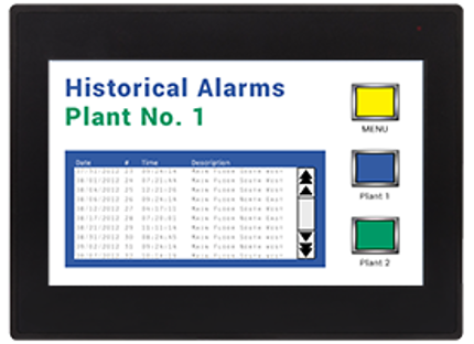
Yes, MAPware-7000 lets you create up to 255 alarms in HMI + PLC (HMC) projects and display them in either a real-time or historical window.Real-time alarms display when certain events in your process occur and show the current status of a process. When real-time alarms are triggered, they remain on the display window until they are acknowledged, or the alarm condition returns to its normal state. Display real-time alarms with different text colors to delineate the state of the alarm (active unacknowledged, active acknowledged, or inactive unacknowledged), severity, date and time, etc.
Historical alarms are a sequential history of your application’s alarm activity. Stored in non-volatile memory, they remain even when the machine is turned off. Historical alarms can be displayed with the severity level, date, and time the alarm occurred, when it was acknowledged, and when it returned to normal. A historical alarm list can also be uploaded to the PC and saved as a CSV file using MAPware-7000.
In Native Ladder, it is recommended to use Internal Registers (BW) for the alarm words. Since the Internal Coils (B) comprise the individual bits of the BW words, they can then be used to trigger the individual alarms. You must create the tags for the alarm words (BW) and the alarm bits (B). The alarm bit (B) tags can be used to trigger alarms in the ladder logic.
In IEC mode, create an Alarm word tag, then create a BOOL array to use with the Set Bit function (Registers) to turn on individual bits in the Alarm word and trigger individual alarms.
Can I set my HMC (HMI + PLC) to act as a Modbus Master and/or a Modbus Slave.
Yes, Maple Systems HMCs (HMI + PLC) can be configured to act as a Modbus Master and/or a Modbus Slave. For step-by-step instructions on how to set up this communication and use tags in your project refer to Tech Note 7016, “Modbus Communications in MAPware-7000”.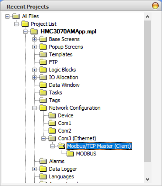
Do you offer warranty on HMI+PLC (HMC) product? Are they repairable?
We offer a one year warranty on our HMI+PLC (HMC) terminals, 90 day warranty on our I/O Modules. These products are repairable for up to 5 years after their obsoletion date.
Can the HMI + PLC (HMC) display Multiple Languages?
Yes. You can configure your project in MAPware-7000 to display up to nine different languages and switch your desired language with an on-screen button. All text and labels will then be displayed in the selected language.
Documents
Manuals
- HMC2043A-M Quick-Start-Guide
- MAPware-7000 Getting Started Guide
- MAPware-7000 Programming Manual
- MAPware-7000 IEC61131 Programming Guide
- HMC Series Installation Guide
- I/O Module Guide for the HMC2000, HMC3000, HMC4000 Series
Certifications
- UL Certification Declaration – HMC2x, HMC3x, HMC4x, HMC7x, MLCx, MLEx, HMI5070L/LB, WP4x
- CE Declaration of Conformity – Web HMI, HMC2X, HMC3x, HMC4x Series
- REACH EU Declaration of Conformity
- RoHS Declaration of Conformity (all series)
- Country of Origin Certification
CAD Files


When you order the HMC2043A-M the following items are included in the box:
- HMC2043A-M
- Warranty Statement
- Installation Instruction
- Product Flyer
- Power Connector
- Mounting Kit

|
Filters |
 4.3" Standard HMI + PLC HMC2043A-M $410 | 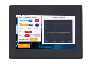 4.3" Advanced HMI + PLC HMC4043A-M $410 |
|---|---|---|
| Loading product data… | ||