Your cart is currently empty!


HMC7-MIO-08
- 4 Analog Inputs (VOLTAGE, CURRENT, RTD, Thermocouple)
- 2 Analog Outputs (VOLTAGE, CURRENT)
- Class I, Division 2 Rated
I/O Expansion Module, 4 AI (Voltage, Current, RTD, Thermocouple), 2 AO (Voltage, Current)
HMC7-MIO-08
There is no direct replacement, see our current HMI+PLC Combo units and expansion modules for upgrade options.
Share the product:
Review this product
Share your thoughts with other customers about this product
|
Filters |

|
|
|
|---|---|---|---|
| Loading product data… | |||
This product is Obsolete – There is no direct replacement. See our HMI+PLC product page for more information.
Converting a MAPware-7000 project from a HMC7000 series model to a HMC3000 series model
Take into consideration the difference in IO modules. If your HMC7000 series project uses IO, these modules will be removed from the IO Allocation folder in the project, yet the tags for the IO module will remain. To automatically remove any unused tags, open the IO Allocation > Expansion window and configure the slot to “Not Installed”. Any tags for that slot that are used in the project will persist though, and the tag use cases must be found using the “tag usage” feature and eliminated.
Because of the difference in IO modules between the HMC7000 and 3000 series, it is important to be prepared to manually convert the IO use cases in the project over to the new IO module tags after they have been configured.
For questions regarding this topic, please contact support@maplesystems.com
How to Convert a project for a HMC3000 Series to a HMC2000 Series model.
Current applications for the HMC3000 series HMI + PLC models that are in IEC programming mode can easily be converted to a HMC2000 series model.
The legacy Native Ladder programming mode is NOT SUPPORTED on the HMC2000 series modes. Projects created in the Native Ladder programming mode will need to be recreated in IEC programming mode for the HMC2000.
1. Open the HMC3000 project in MAPware-7000 v2.36 or later.
2. Select “Tools” > “Convert Application…” to open the project conversion window.

3. Select the product and model for the conversion from the drop-down menu, name the project and set a file path.
4. Click “Convert”. At this point, if the project is in Native Ladder mode, the following error message will appear:

5. If the project is in IEC mode, it will convert. After the conversion process, a file called “ConversionLogs.txt” will appear. The logs in this file are not necessarily errors, just entries indicating that the graphic objects were not resized or unused default tags were deleted from the tag database. You can save or close the log file.

6. Next, confirm that the project will compile by clicking “Project” > “Compile” and check the terminal window for errors. If the original HMC3000 application compiled without errors, then the converted project should as well.
7. Scan the screens in your application to make sure that graphic objects are aligned correctly and not outside of the frame. This is only necessary for projects that were converted to another screen size.
8. If any changes were made, save the project. Now the project can be downloaded to the new HMC2000 screen.
Do the Maple Systems HMI+PLCs (HMC) support High-Speed Counters (HSC)?
Yes. Our HMI+PLCs (HMC) support High-Speed Counters in MAPware-7000. See the specific Series IO Module guide for more information on which IO modules support High-Speed Counters (HSC) and what registers are used for configuration. Most supported IO modules offer 2 or 4 high speed inputs. Both quadrature and standard HSCs are supported. When using HSCs, different product lines have different maximum frequencies ranging from 10 kHz to 200 kHz.Do the Maple Systems HMI+PLCs (HMC) support Pulse Width Modulation (PWM)?
Yes. Our HMI+PLCs (HMC) support Pulse Width Modulation in MAPware-7000. See the specific Series IO Module guide for more information specifics on which IO modules support Pulse Width Modulation (PWM) and what registers are used for configuration. Four modes of PWM are supported for most IO modules; Normal, Clockwise/Counter-Clockwise (CW/CCW), Pulse/Direction, and Trapezoidal (Fixed Pulse). When using PWM outputs, different product lines have different maximum frequencies ranging from 1 kHz to 200 kHz. Tech Note 7009, “Pulse Width Modulation”, describes each of the four types of PWM output, and then lists which registers to configure, how to configure those registers, and the minimum and maximum ranges of each register. Review the IO module specification sheets to ensure PWM is available.Why is my I/O module not working properly?
Most I/O modules require a separate +24VDC power supply connection. See the appropriate Series I/O Module Guide to locate this connection on a specific I/O module.Analog inputs and outputs require writing a value to a corresponding configuration register to program the I/O for 4-20 mA, 0-10V, RTD, etc. Although there is a Configuration option when adding an I/O module in the Expansion IO Allocation window, if the I/O module isn’t operating properly, we recommend using Power-On Tasks to write the appropriate values to the configuration registers at startup.
Also, it may be necessary to update the firmware in the I/O module. See Tech Note 7008, “Update HMC7000 Series Expansion Module Firmware,” for instructions on how to do this.
How to transfer a MAPware-7000 project
These instructions describe the process required to email your HMC or MLC project file or transfer it to a different directory.
In order to open the project when it has reached it’s destination, both the *.mpl file and the folder with the same name need to be in the same directory:

Both files will be stored into a main project folder already when saved in MAPware-7000. Locate that save folder, the right click and create zip file.

Now the project can be emailed or moved to a different PC properly.
I'm having trouble downloading to my HMI+PLC (HMC) from a USB Flash Drive.
Tech Note 7012, “Download a Project to an HMC from a USB Flash Drive,” provides step-by-step instructions.
I'm having trouble downloading to or configuring my HMI+PLC (HMC) using a USB cable – Download Issue/Error/Problem
If you experience difficulty downloading to an HMI+PLC (HMC) from MAPware-7000 with a Windows® 10 operating system, you may need to re-install the MAPware-7000 USB Drivers. The MAPware-7000 USB drivers are located in the folder: C:MapleSystemsMAPware7000USB Drivers. Refer to Tech Note 7017, “Reinstall MAPware-7000 USB Drivers” for full instructions on how to delete and reinstall the USB driver. Also, make sure you are using a USB 2.0 port on your PC to download to the HMI+PLC. USB 3.0 is not supported.Trying to download but MAPware7000 says "Device not responding"
If you are attempting to download to an HMI/PLC and the download manager displays “”Device not responding””, check that the physical connection between the HMC and PC is secure.If using Ethernet, make sure the PC can connect to the HMC by “PINGing” the IP address of the HMC.
If using USB, confirm that “HMI USB Device” shows up in Windows Device Manager. You may want to refer to Tech Note 7017 AFTER considering the next step.
On the HMC screen, delete the firmware by holding the top left corner of the screen while powering on. Then delete the application by holding the top right corner of the screen while powering on. Now try downloading the project to the screen again.
Software Downloads & Upgrades
Manuals & Guides
- HMC Series Installation Guide
- MAPware-7000 Programming Manual
- MAPware-7000 Ladder Logic Guide
- Mapware-7000 Getting Started Guide
- HMC3000 I/O Module Guide
- HMC7000 I/O Module Guide
- MAPware-7000 IEC61131 Programming Guide
Videos
- Part 1: Introduction and Installation
- Part 2: Creating a Native Ladder Project
- Part 3: Adding and Initializing Tags
- Part 4: Adding Logic
- Part 5: Creating an HMI Screen
- Part 6: Duplicationg an HMI Screen
- Part 7: Downloading and Testing the Project
- Part 8: Creating an IEC Project
- Part 9: Creating a UDFB
- Part 10: Adding a Structure Text UDFB
- Part 11: Adding Power Up and Main Routine Logic
- Part 12: Creating Screen Objects
- Part 13: Downloading the Project and Online Monitoring
Sample Projects
-
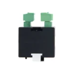
 I/O Module | 8 Bi-Directional Digital Inputs, 8 Digital Outputs, 4 Analog Inputs, 1 Analog Output, Thermo/RTD$295.00
 -
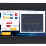 7.0″ Advanced HMI + PLC$550.00
-
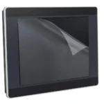 Screen Protector, 7.0” (153mm x 92mm) 1 each.$20.00
 -
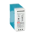 Power Supply, Single Output, DIN Rail Mountable. Input: 100-240VAC, 1.1A/Output: 24VDC, 1.7A.$40.00