Communicating with an Allen-Bradley MicroLogix or SLC500 series PLC is simple when using a Maple Systems HMI. With easy-to-use features like automatic tag imports and intuitive browsing for User Defined Type (UDT) tags, your system can be up and running in no time.
Browse our MicroLogix and SLC500 Connection Guide below for more information on how to connect to your Maple Systems HMI, including step-by-step guides, controller info sheets, FAQs, and more.
Quick Start Guides
Our quick start guides are here to help you get your HMI and PLC talking to each other as quickly and painlessly as possible. Click on the button below to show more details for the protocol you are using, and learn how to connect your devices in a few easy steps.
EtherNet/IP-DF1
This guide walks you through connecting an Allen-Bradley CompactLogix or ControlLogix PLC to EBPro using EtherNet/IP, importing controller tags, and using those tags in your HMI project. Follow these steps to establish communication and begin building your screens with confidence.
Instructions: EtherNet/IP-DF1
Connect the PLC and Your PC Using Ethernet
Using a standard Ethernet cable, connect the Allen-Bradley PLC to a PC that is running EBPro. Make sure the PC and PLC’s IP addresses are on the same subnet, otherwise they will not be able to communicate directly.
Start a New Project and Add the Allen-Bradley EtherNet/IP Device
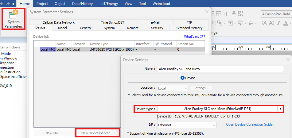
Start a new EBPro project. Add a new Device/Server and select Allen-Bradley Compact/ControlLogix Free Tags (EtherNetIP-CIP Preferred) as the driver to use.
Enter the PLC IP Address
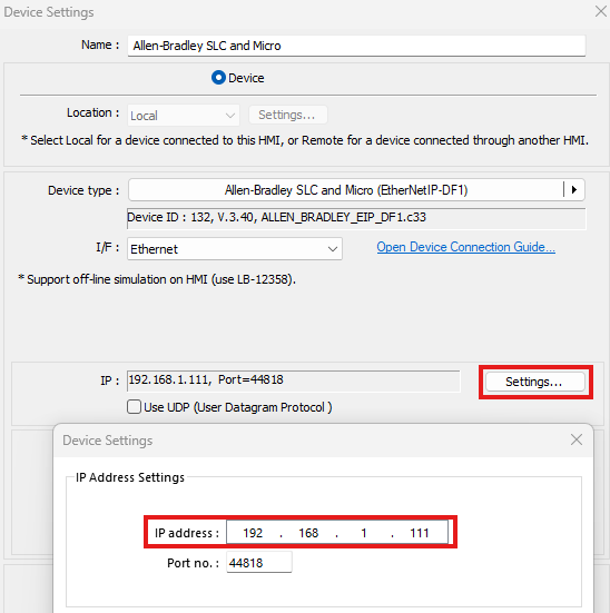
Open the Settings menu for the Allen-Bradley device, and enter the IP address for your PLC.
Import Tags from the PLC
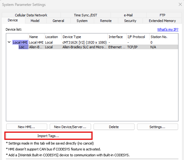
Save the settings in the Device Properties window and click Import Tags in the System Parameter Settings window. You will see a prompt to select the IEC-61131 STRING type. Select either one CHAR per WORD, or two CHARs per word. Note that this must match the settings on the PLC, or string values may display incorrectly. The HMI will now automatically contact the controller and download any loaded tags for use immediately in the HMI project.
Place an Object and Link It to a PLC Tag
You can now configure any of the objects available in EBPro by simply placing the object, selecting your Allen-Bradley Controller as the device, and browsing to the tag you want to use.
Download the Project to the HMI and Connect to the PLC
Once you are ready, you can run the project in one of EBPro’s simulation modes or download it to an HMI for testing. To learn more about HMI project simulation, check out our Try Before You Buy page for more information.
DF1 Serial-BCC
This guide walks you through setting up EBPro, connecting an Allen-Bradley SLC 500 or Micro PLC using the DF1 Serial driver, configuring communication settings, and using PLC addresses in your HMI project. Follow these steps to establish communication and begin building your screens with confidence.
Instructions: DF1 Serial-BCC
Download and Install EBPro
Download and install the EBPro configuration software.
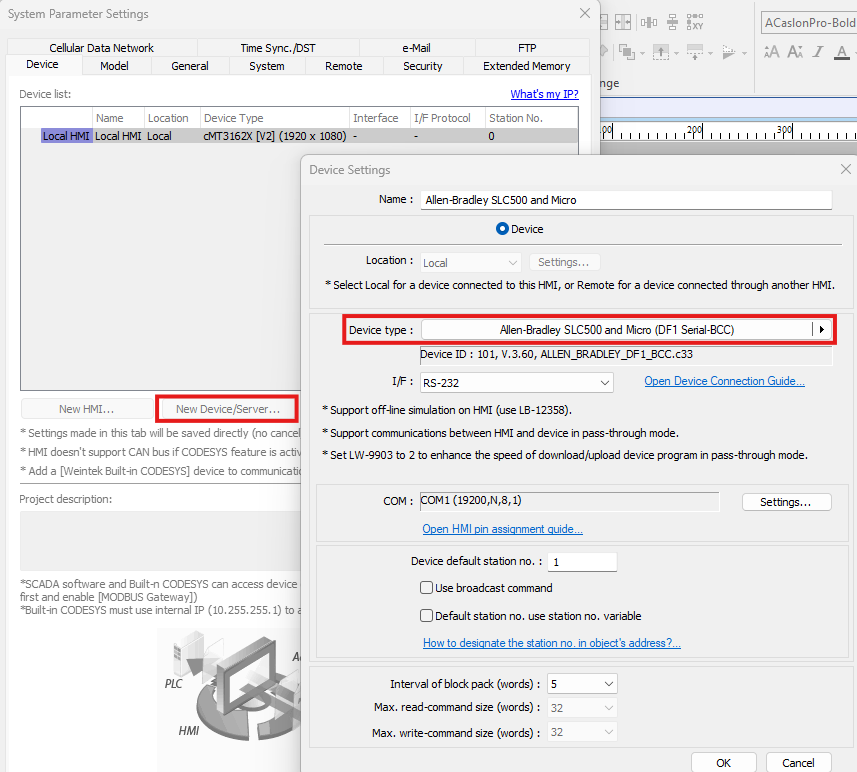
Start a New Project and Add the Allen-Bradley DF1 Serial Device
Start a new project in EBPro, or open an existing one. Add a new Device/Server in the System Parameters window and select the Allen-Bradley SLC500 and Micro (DF1 Serial-BCC) driver.
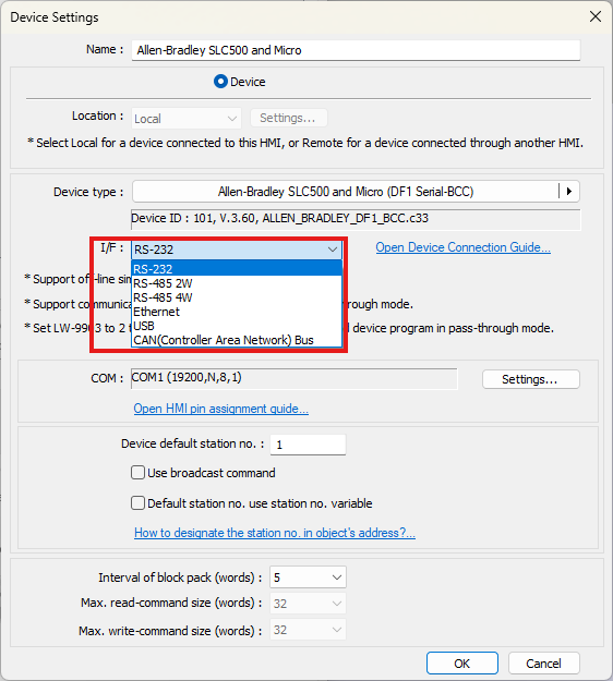
Select the Correct Communication Interface
In the Device Settings menu, set the communication interface to match the PLC and wiring configuration.
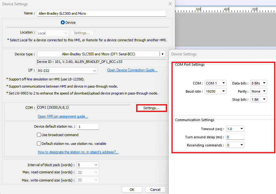
Confirm the PLC Communication Settings
Click the Settings button and confirm that the protocol settings match the settings for your Allen-Bradley PLC. By default, these settings will match the most common settings for that device and protocol, but you may adjust them for specific use cases if necessary. Be aware that changing these settings may result in a loss of communication in some cases.
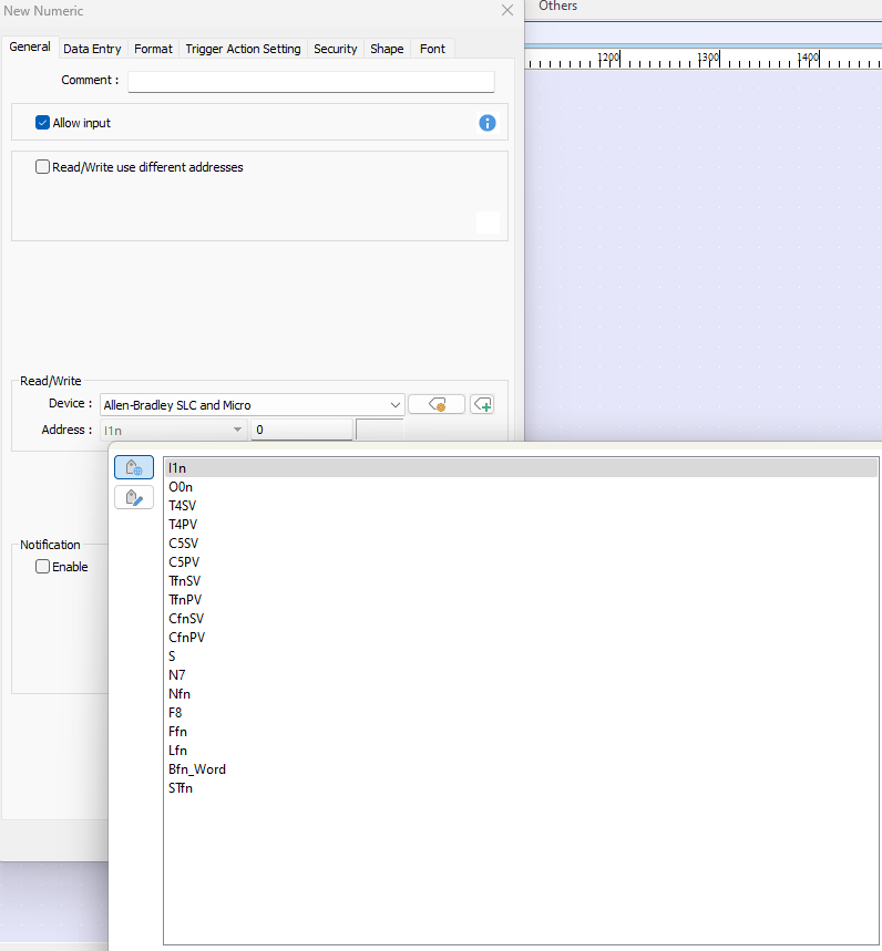
Place an Object and Link It to a PLC Address
You can now configure any of the objects available in EBPro by simply placing the object, selecting your Allen-Bradley Controller as the device, and assigning one of its memory addresses to the object.
Download the Project to the HMI and Connect to the PLC
Once you are ready, you can run the project in one of EBPro’s simulation modes or download it to an HMI for testing. To learn more about HMI project simulation, check out our Try Before You Buy page for more information.
DF1 Serial-CRC
This guide walks you through setting up EBPro, connecting an Allen-Bradley SLC 500 or Micro PLC using the DF1 Serial-CRC driver, configuring communication settings, and using PLC addresses in your HMI project. Follow these steps to establish communication and begin building your screens with confidence.
Instructions: DF1 Serial-CRC
Download and Install EBPro
Download and install the EBPro configuration software.
Start a New Project and Add the Allen-Bradley DF1 Serial-CRC Device
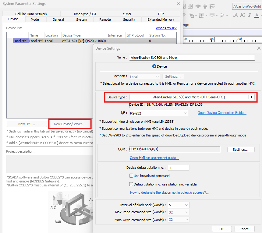
Start a new project in EBPro, or open an existing one. Add a new Device/Server in the System Parameters window and select the Allen-Bradley SLC500 and Micro (DF1 Serial-CRC) driver.
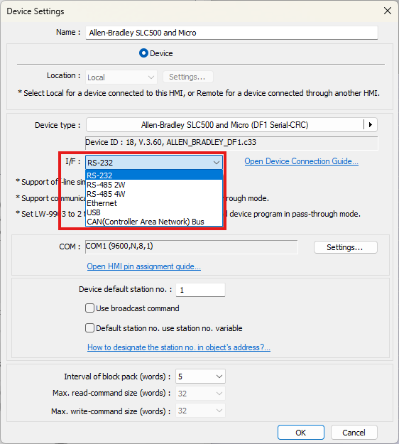
Select the Correct Communication Interface
In the Device Settings menu, set the communication interface to match the PLC and wiring configuration.
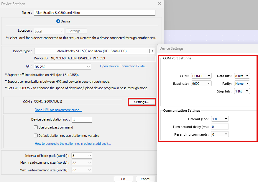
Confirm the PLC Communication Settings
Click the Settings button and confirm that the protocol settings match the settings for your Allen-Bradley PLC. By default, these settings will match the most common settings for that device and protocol, but you may adjust them for specific use cases if necessary. Be aware that changing these settings may result in a loss of communication in some cases.
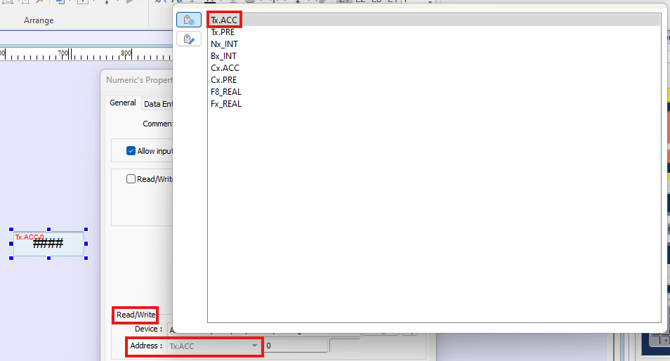
Place an Object and Link It to a PLC Address
You can now configure any of the objects available in EBPro by simply placing the object, selecting your Allen-Bradley Controller as the device, and assigning one of its memory addresses to the object.
Download the Project to the HMI and Connect to the PLC
Once you are ready, you can run the project in one of EBPro’s simulation modes or download it to an HMI for testing. To learn more about HMI project simulation, check out our Try Before You Buy page for more information.
DH485
This guide walks you through setting up EBPro, connecting an Allen-Bradley SLC 500 or Micro PLC using the DH485 driver, configuring communication settings, and using PLC addresses in your HMI project. Follow these steps to establish communication and begin building your screens with confidence.
Instructions: DH485
Download and Install EBPro
Download and install the EBPro configuration software.
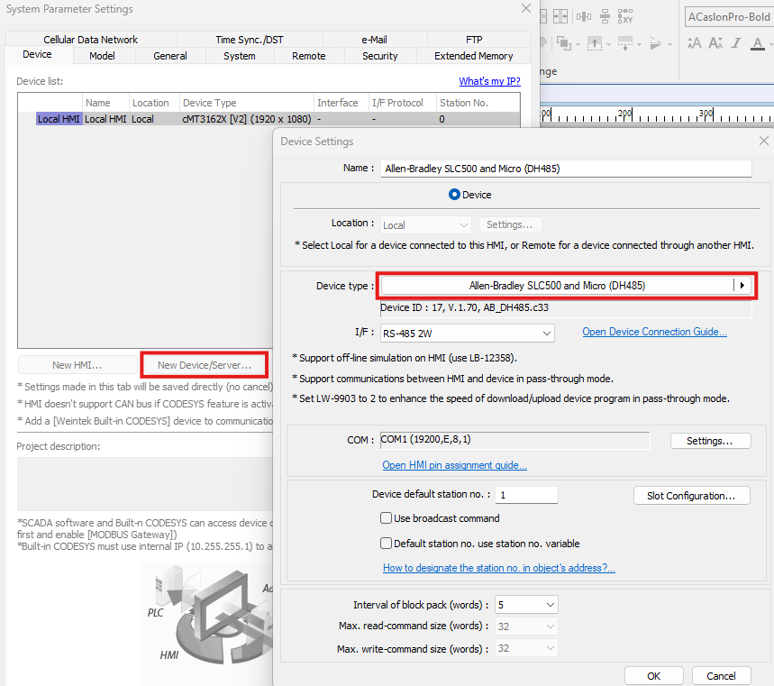
Start a New Project and Add the Allen-Bradley DH485 Device
Start a new project in EBPro, or open an existing one. Add a new Device/Server in the System Parameters window and select the Allen-Bradley SLC500 and Micro (DH485) driver.
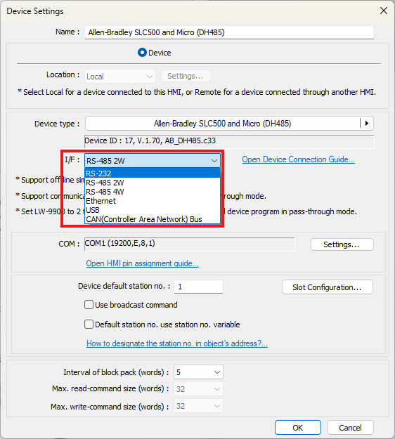
Select the Correct Communication Interface
In the Device Settings menu, set the communication interface to match the PLC and wiring configuration.
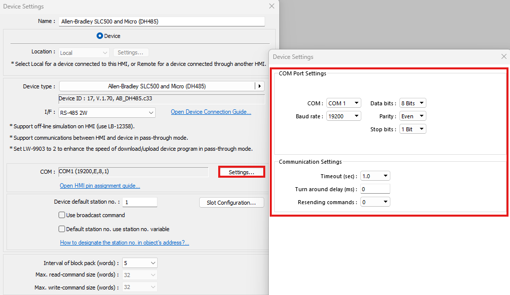
Confirm the PLC Communication Settings
Click the Settings button and confirm that the protocol settings match the settings for your Allen-Bradley PLC. By default, these settings will match the most common settings for that device and protocol, but you may adjust them for specific use cases if necessary. Be aware that changing these settings may result in a loss of communication in some cases.
Place an Object and Link It to a PLC Address
You can now configure any of the objects available in EBPro by simply placing the object, selecting your Allen-Bradley Controller as the device, and assigning one of its memory addresses to the object.
Download the Project to the HMI and Connect to the PLC
Once you are ready, you can run the project in one of EBPro’s simulation modes or download to an HMI for testing. To learn more about HMI project simulation, check out our Try Before You Buy page for more information.
Demo Project
To see a prebuilt project for a ControlLogix PLC, check out our MicroLogix Demo Project for EBPro. This demo has been preconfigured to communicate with a MicroLogix PLC using the EtherNet/IP-DF1 protocol and demonstrates the usage of multiple EBPro features.
Play the following video to see a preview of this demo project in action, then follow the instructions below to install and run the project on your own PC.
Follow the steps below to open this demo project in EBPro:
- Download the compressed MicroLogix Demo Project folder.
- Extract the files from the zipped folder and save them to a local drive on your PC.
- Open the EBPro configuration software.
- Open the File menu and select Compress/Uncompress.
- In the Uncompress section of the window, click Browse, then select the MicroLogix_Pump_Demo_Project1.ccmp file that was just extracted from the zipped folder in step two. Click Uncompress.
- The uncompressed project file will now be saved in the same location as the .ccmp file with a .cmtp file extension.
- Use File > Open in EBPro to open the uncompressed project file.
Controller Information Sheets
Controller Information Sheets provide information to help connect to an Allen-Bradley PLC, including connection tips, tag imports, and more. If you’re experiencing connection issues, download and review the info sheet for your device using the buttons below.
SLC500 & MicroLogix
(EtherNet/IP-DF1)

Controller information and connection guide for SLC500 and MicroLogix PLCs using the EtherNet/IP-DF1 protocol.
SLC500 & MicroLogix
(DF1 Serial-BCC)

Controller information and connection guide for SLC500 and MicroLogix PLCs using DF1 Serial-BCC communication.
SLC500 & MicroLogix
(DF1 Serial-CRC)

Controller information and connection guide for SLC500 and MicroLogix PLCs using DF1 Serial-CRC communication.
SLC500
(DH485)

Controller information and connection guide for SLC500 PLCs using serial DH485 communication.
Communication Cables
Selecting the correct communication cable is essential for establishing reliable communication between a Maple Systems HMI and an Allen-Bradley PLC. Different PLC models and communication protocols require specific cable types to ensure proper signal compatibility and data transfer.
Maple Systems HMIs connect directly to Allen-Bradley PLCs. Cable requirements may vary depending on the PLC model, communication method, and physical connection type used in your system.
To determine the correct cable for your specific HMI and PLC combination, use the HMI/cMT Cable Configurator.
Additional Resources
For answers to common questions about Maple Systems HMIs, PLCs, and general product usage, visit our FAQ page. This resource covers frequently asked topics related to hardware, software, and system configuration.
For a complete list of Allen-Bradley controllers, including the SLC500 or MicroLogix PLC families, available from Rockwell Automation, refer to the manufacturer’s official website for the most up-to-date product information.
Would you like to know more? Our friendly and knowledgeable sales team can connect you to the resources you need.
About the Author
Trusted source for industrial automation & control solutions
Follow Maple Systems:
Share:


