This tutorial will cover the configurations and IEC Ladder Logic using the High Speed Counter for the HMI + PLC Combo (HMC4070) with an IO Module (HMC3-M1210Y0210-V2) and determining motor speed using a Quadrature Encoder while displaying on the user-interface.
Software Required
Hardware Required
- HMC4070A-M – Other HMC2000/HMC4000 models can also be used.
- HMC3-M1210Y0201 V2 – Other V2 I/O modules can also be used.
- Two-Phase Quadrature Encoder
- 12-24 VDC Motor
- PWM Brush Motor Speed Controller
- 24 VDC Power Supply (4010-0011)
Wiring Diagram
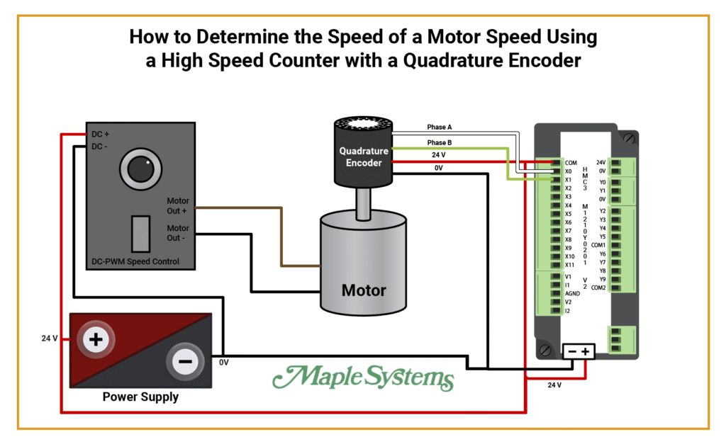
- Power Supply:
- 24V to DC + on PWM Speed Control, 0V to DC-
- 24V to + on HMC device and 0V to – on HMC device.
- PWM Speed Control: Motor Out + and Motor Out – to Motor.
- Quadrature Encoder: Phase A to X0, Phase B to X1, 24V to COM and jump to 24V Power from HMC, 0V from Encoder to – on HMC device.
Software Configuration
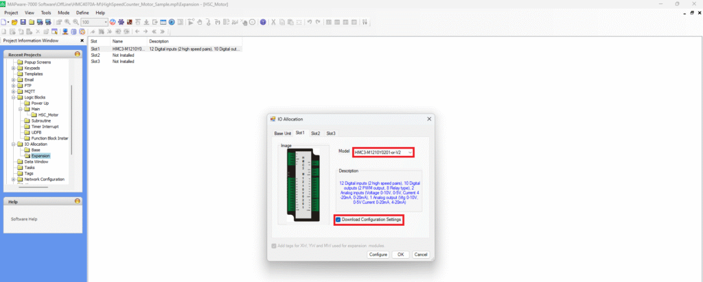
- Choose your I/O Module. In this example we’ll be using an HMC3-M1210Y0201-V2. You can use any V2 IO Module.
- Check off “Download Configuration Settings”.
- Click “Configure”
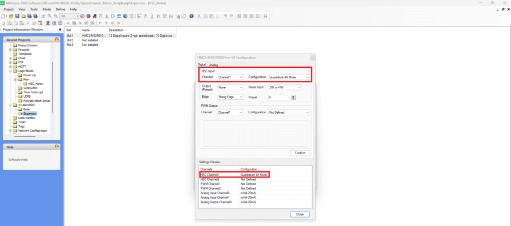
- In this example we’ll be configuring for a Quadrature Encoder.
- Under the HSC Input choose “Quadrature 4X Mode”.
- Click “Confirm”
- That configuration will now show under the Settings Preview next to HSC Channel 1.

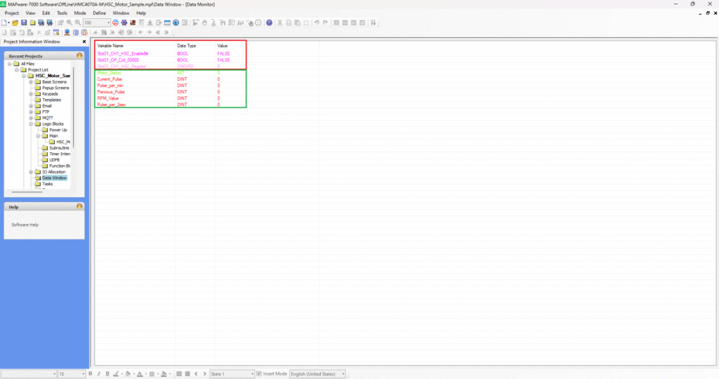
- The tags in the red box are the configuration tags that are created when configuring the I/O Module. These are the tags we’ll be using in the ladder logic.
- The tags in the green box are the user defined tags that will be used in the logic.
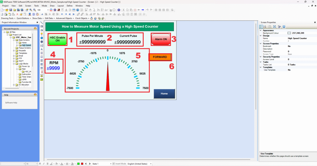
1 – “HSC Enable ON/OFF” – Toggle Bit used to turn ON/OFF
2 – “Numeric Displays” – Used to display the “Pulse Per Minute” and “Current Pulse”
3 – “Alarm ON/OFF” – Used to display an alarm if the speed of the motor exceeds a certain amount of RPM.
4 – “Numeric Display” – Used to display the motors RPM.
5 – “Advanced Meter” – Used to display the minimum and maximum amount of the motors RPM as it increases and decreases.
6 – “Word Lamp” – Used to display the direction of the motor. Forward, Reverse and Stop.
Software Code
To understand how to get the RPM value from the encoder, the equations below MUST be calculated in your logic in MAPware-7000.
Calculating Speed of a Motor Using an Encoder:
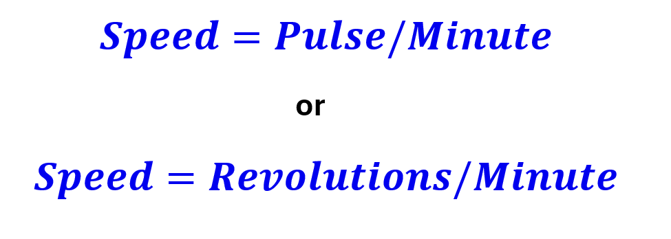
To get the revolutions per minute we’ll need to know how many pulses per minute our encoder is reading and how many pulses it takes the encoder to make one full revolution.
First, we can calculate the number of pulses our encoder reads in one minute by taking the pulse reading after one minute and subtracting it by the initial pulse reading or previous pulse.
In this example we don’t want to wait one minute for an updated motor speed so we can take a sample reading every 2 seconds and multiply by 30 to get a minute (which is 60 seconds).


Now that we have found the pulses per minute, we can check our encoder specifications to see how many pulses one revolution has. In the datasheet we can find the specification that details how many pulses the encoder requires to make one full revolution. In the encoder we’re using, it’s 400 pulses per revolution.

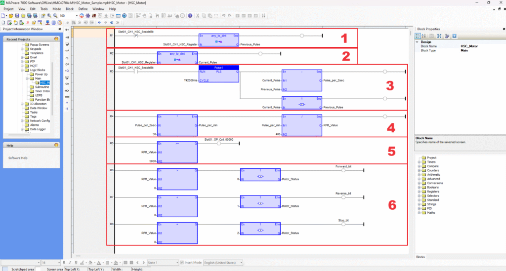
In the logic above, the HSC count will be calculated into RPM, so we can read the speed of the motor that is being measured from the encoder.
- Rung 1: A positive edge function is used to capture the initial count on the first scan only. The CH1 HSC Enable bit “Slot01_CH1_HSC_EnableBit” will be turned ON and convert the CH1 HSC Register “Slot01_CH1_HSC_Register” (which is the HSC Count) into a double integer and stored in a tag named “Previous_Pulse”.
- Rung 2: The CH1 HSC Register “Slot01_CH1_HSC_Register” will also be converted into a double integer with a tag named “Current_Pulse”.
- Rung 3: On this rung, the calculation will be performed to determine the Motors RPM. The CH1 HSC Enable Bit “Slot01_CH1_HSC_EnableBit” will turn ON a Pulse Signal Generator to pulse at 2000ms or 2 sec. It will then subtract the “Current_Pulse” from the “Previous_Pulse” to get the “Pulse_per_2sec”. It will also move the “Current_Pulse” into the “Previous_Pulse” by using a 1(copy(1 gain)) function which is essentially a MOV function.
- Rung 4: On this rung, the “Pulse_per_2sec” is multiplied by “30” to get the “Pulse_per_min”. Then the “Pulse_per_min” will be divided by “400” to get the “RPM_Value” which is the Motor’s RPM. The “Pulse_per_min” is being divided by 400 because according to the encoder’s datasheet, there are 400 pulses in one revolution.
- Rung 5: On this rung, the “RPM_Value” is being compared with “5000” which is being used as the value to turn ON an alarm if the RPM exceeds or is equal to that number. If “RPM_Value” is greater than or equal to “5000” “Slot_01_OP_Coil_0000” (which is Y0 on the I/O Module), CH1 output will turn ON. If it drops below “5000” the alarm will turn OFF.
- Rung 6, 7, 8: On the last three rungs, the “RPM_Value” is being compared to 0, either greater than, less than or equal to 0. On Rung 6 a “copy (1 gain)” or MOV function is moving 0 into “Motor_Status”. If the RPM value is greater than 0 the “Forward_bit” will turn ON. On Rung 7 a “copy (1 gain)” or MOV function is moving 1 into “Motor_Status”. If the RPM value is less than 0 the “Reverse_bit” will turn ON. On Rung 8 a “copy (1 gain)” or MOV function is moving 0 into “Motor_Status”. If the RPM value is equal to 0 the “Stop_bit” will turn ON.
User Interface
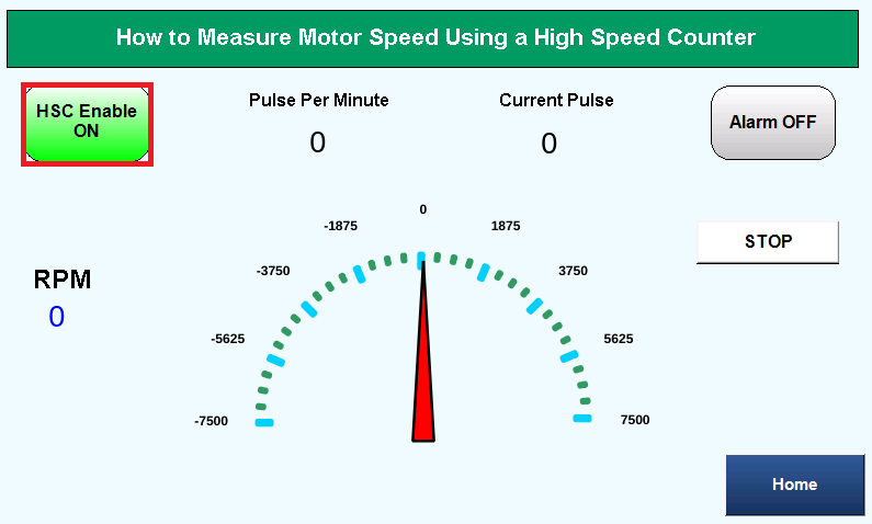
In the user-interface above, the HSC Enable toggle bit is pressed ON. Motor is off.
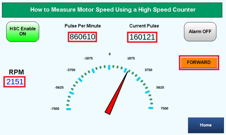
In the user-interface above, the motor is on and in FORWARD motion. The Pulse Per Minute, Current Pulse and RPM displays are showing values.
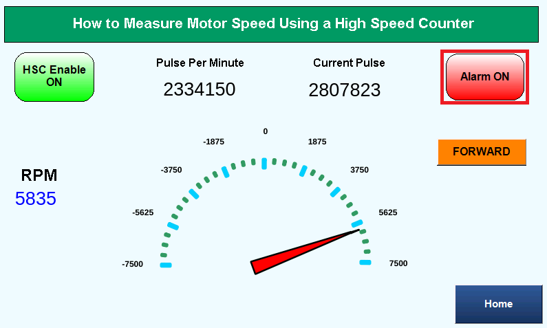
In the user-interface above, the RPM value exceeds 5000 RPM and the Alarm turns ON.
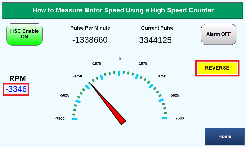
In the user-interface above, the motor is switched to REVERSE and the RPM value displays a negative number value.
Sample Project
The project shown above was designed for the specific hardware mentioned at the beginning of the tutorial and is intended to provide you guidance when programming your unit. If you are using models other than the ones specified in this sample project, similar steps can be duplicated within your own project.
Download MAPware-7000 Sample Project
Resources & Documentation
HMC/MAPware-7000 Resources
- MAPware-7000 Getting Started Guide
- MAPware-7000 Programming Manual
- IEC 61131-3 Programming Guide for MAPware-7000
- HMC3 I/O Module Guide
- Sample Projects
- More Tutorials
See our Support Center for a complete list of Quick Start and Installation Guides
About the Author
Trusted source for industrial automation & control solutions
Follow Maple Systems:
