Your cart is currently empty!
How to Control Motor Speed Using a PID Loop, Pulse Width Modulation and a High Speed Counter
In this tutorial, you will learn how to utilize a PID, Pulse Width Modulation (PWM), and a High-Speed Counter to control motor speed. The PID will function in a closed-loop system, controlling the PWM and using the high-speed counter (RPM) as the feedback response. The PID will control and maintain a precise rotation speed, all of which will be configured in the control software, MapleLogic.
Please review these tutorials if you are unfamiliar with the functionalities of a PID, PWM and HSC in MapleLogic.
How to Control the Temperature of a Heater using a PID Loop
What is a High Speed Counter and How is it Used with an Encoder?
What is Pulse Width Modulation?
How to Control the Speed of a Motor Using Pulse Width Modulation
If you are familiar with the tutorials above, please continue on with this tutorial.
Software Required
Hardware Required
- Maple Modular PLC’S – Any Maple Modular PLC can be used.
- PWM Module + Kit – A terminal block MUST be used with the PWM Module.
- HSC Module + Kit – A terminal block MUST be used with the HSC Module.
See the wiring and configuration below. - Two-Phase Quadrature Encoder – Encoder Model used in this example: C38HG5-100B-G24N
- 12-24V DC Motor – Motor Model used in this example: XD-3420
- DC Motor Drive Module – Drive Module used in this example: 200206_FBA
- (2) 24 VDC Power Supply (4010-0011)
Wiring Diagrams
The diagram below is a detailed wiring design to measure the speed of a motor using a PID Loop, Pulse Width Modulation and a High Speed Counter. The Maple Systems PLC is connected to a PWM and HSC Module. Both the HSC and PWM Modules are connected to terminal blocks. A quadrature encoder is wired into the HSC Module terminal block. A PWM signal is sent from the PWM Module to a DC Motor Drive Module into a 24V DC Motor.
See the wiring table below.


Please note that a 2nd power supply was used in this example, but you can use one power supply based on the amount of current being provided.
HSC Module Configuration
Below, we will be configuring the parameters for the High Speed Counter Module (IO-SHSC02) in MapleLogic.
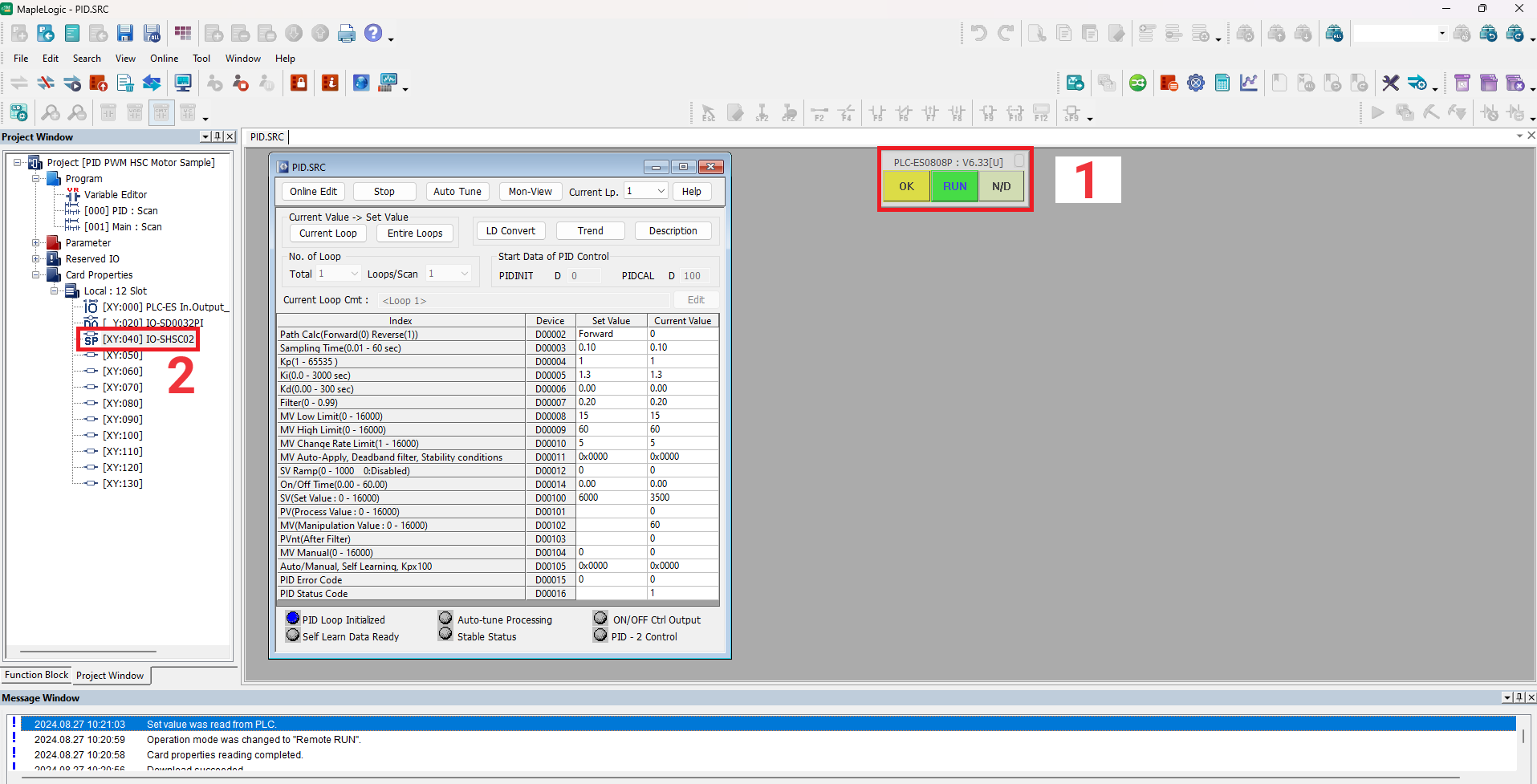
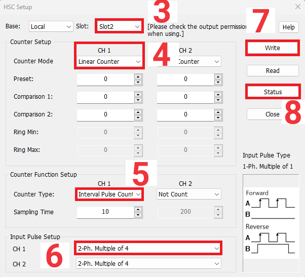
Above is an image of the HSC Module Configuration GUI. This can only be accessed when online with the PLC.
1 – Notice, the PLC is online and in RUN mode. The PLC MUST be online to configure the HSC Module.
2 – Double click the IO-SHSC02 under the “Local: 12 Slot” to open the HSC Configuration GUI.
3 – The slot number will be automatically detected. In this case the HSC Module is in Slot 2.
4 – The Counter Mode can either be Linear or Ring. To learn about these two modes please refer to the What is a High Speed Counter and How is it Used with an Encoder? Tutorial. In this example, a Linear Counter will be used to count in one direction.
5 – The Counter Function Setup is selected next. If one of these is not selected, you WILL NOT receive a count. Select Periodic Pulse Count to count the pulses from the encoder. Sampling Time is used to set up the time and the interval of sampling when sampling counting, or periodic pulse counting is used.
6 – For the Input Pulse Setup select the 2-Phase. Multiple of 4 for a Quadrature Encoder.
7 – Click “Write” to save the settings.
8 – Click “Status” to view the live values.
PID Configuration
To get a better understanding of a PID please refer to the What is a PID Controller Tutorial Page.
For a more detailed description on the PID Configurations please refer to the How to Control the Temperature of a Heater using a PID Loop Tutorial Page to learn more about the PID configurations in MapleLogic.
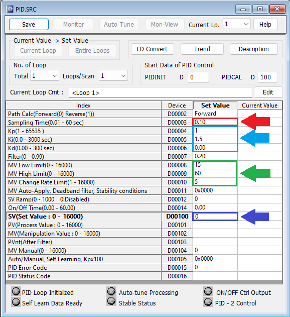
- In this demo, we will be setting a low sampling time.
- The Kp and Ki will also be set low. The Kp and Ki values were determined through a previous trial-and-error process. The values for your PID system may be different.
- The MV Low Limit will be set to 15 and High Limit set to 60. Even though the PWM Module can output 0-100% Duty Cycle, the motor being used in this example can only interpret a difference between 15% and 60%. This is just a mechanical limitation for the motor used in this sample project and was determined through a trial-and-error process. The MV Change Rate Limit will update every 5 seconds.
- The set value is 0. This value will be determined by automated ladder logic.
Ladder Logic
In the following logic, we will enable the PWM channel and high-speed counter, calculate the RPM, and send the PWM duty cycle and RPM values to the PID registers, allowing the PID to control the motor speed.
Enabling PWM
For a more detailed description please refer to the How to Control the Speed of a Motor Using Pulse Width Modulation Tutorial Page to learn more about the PWM configurations in MapleLogic.
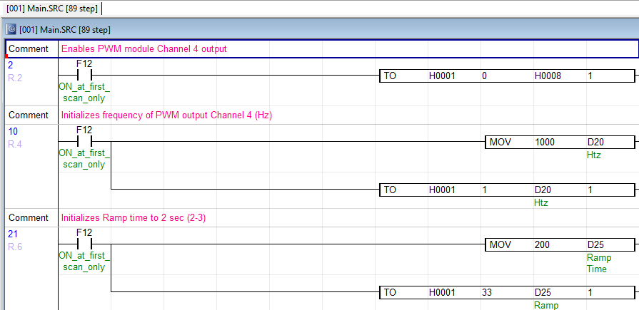
Rung 2 – Enables the PWM Module output CH 4
Rung 4 – Initializes the frequency (Hz) for PWM output CH 4
Rung 6 – Initializes the Duty Cycle Ramp Time (2 Sec) for PWM output CH 4
Enabling and Starting the High Speed Count
Please refer to the HSC Module Internal Memory in the MapleLogic Help Files to enable the count and start the count.
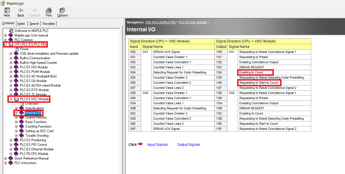

Rung 8 – Enables the HSC count and starts the HSC. We are enabling (Y44) and (Y46) because the HSC Module is located in Slot 2 of the I/O Chassis. These two registers must be enabled from the HSC Module internal memory.
Calculating the RPM Value
Please refer to the HSC Module Shared Memory in the MapleLogic Help Files to get the buffer memory for the Current Count, Periodic Pulse Count and Current Pulse Count.
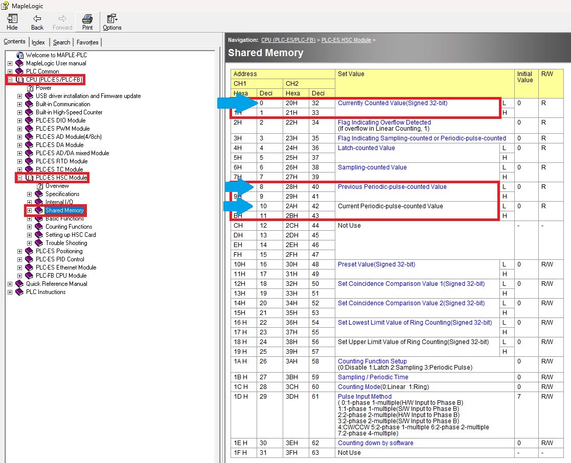
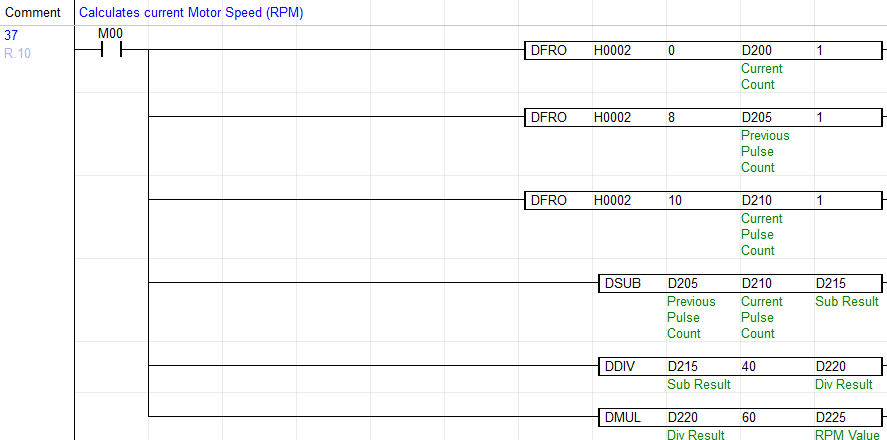
The first three lines of logic in Rung 10 are “DFRO” application instructions. “DFRO” is a double word “FROM” instruction to get the current count, previous pulse count and current pulse count from the encoder.

All three are 32 bits so you need to use the DFRO to get the correct reading from the encoder. This means that grabbing buffer memory “0” for the current count will also grab “1”. Buffer memory “8” will also grab “9”. Buffer memory “10” will also grab “11”.
The next three lines is the arithmetic application instructions to receive the RPM value, which we will then send to the Manipulative Value for the PID in the next section.

The first line subtracts the current pulse “D210” double word from the previous pulse “D205” double word and stores that result in “D215”.
The second line divides the subtraction result “D215” by 40 and stores the result in “D220”. We are using 40 because that represents 40 pulses for 10 milliseconds. 10 is referring to the Sampling Time we entered earlier in the HSC Module GUI. The encoder actually reads 400 pulses per one revolution but to get a more precise RPM value, we changed it read 40 pulses every 10 milliseconds.
The third line multiplies the divided result by 60. 60 represents 60 seconds or 1 minute. This is to get the rotations per minute from the encoder. The result is stored in D225.
Moving the RPM Value into the PID Process Value (PV)

Rung 12 – Sends the RPM value “D225” into the PID Process Value “D101”.
Automation Example
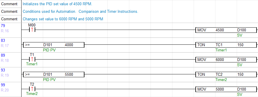
Rung 16 – When M00 is enabled, 4500 RPM will move into the Set Value “D100“.
Rung 17 – If “D100” is greater than or equal to 4000, a 15 second ON timer will be triggered.
Rung 18 – At 15 seconds, a value of 6000 RPM (increase speed) will move into the Set Value “D100“.
Rung 19 – If “D100” is greater than or equal to 5500, a 15 second ON Timer will be triggered.
Rung 20 – At 15 seconds, a value of 5000 RPM (decrease speed) will move into the Set Value “D100“.
Moving the Manipulative Value (MV) to the PWM Duty Cycle

Rung 22 – Sends the CH.4 PWM Duty Cycle (13) to the Manipulative Value for the PID, so that the PID can control the Duty Cycle.
Online Simulation
In this online demo, we will be simulating the automated logic for an industrial application example such as a motor driving a conveyor belt. In a real scenario, a conveyor belts speed must be adjusted based on different operating conditions, such as varying loads. Based on the amount of load, the motor will need to increase or decrease speed. The usage of comparison, move and timer instructions in ladder logic, is one way to simulate these conditions.
Establish online communication.
Online > Link+Download+Monitor
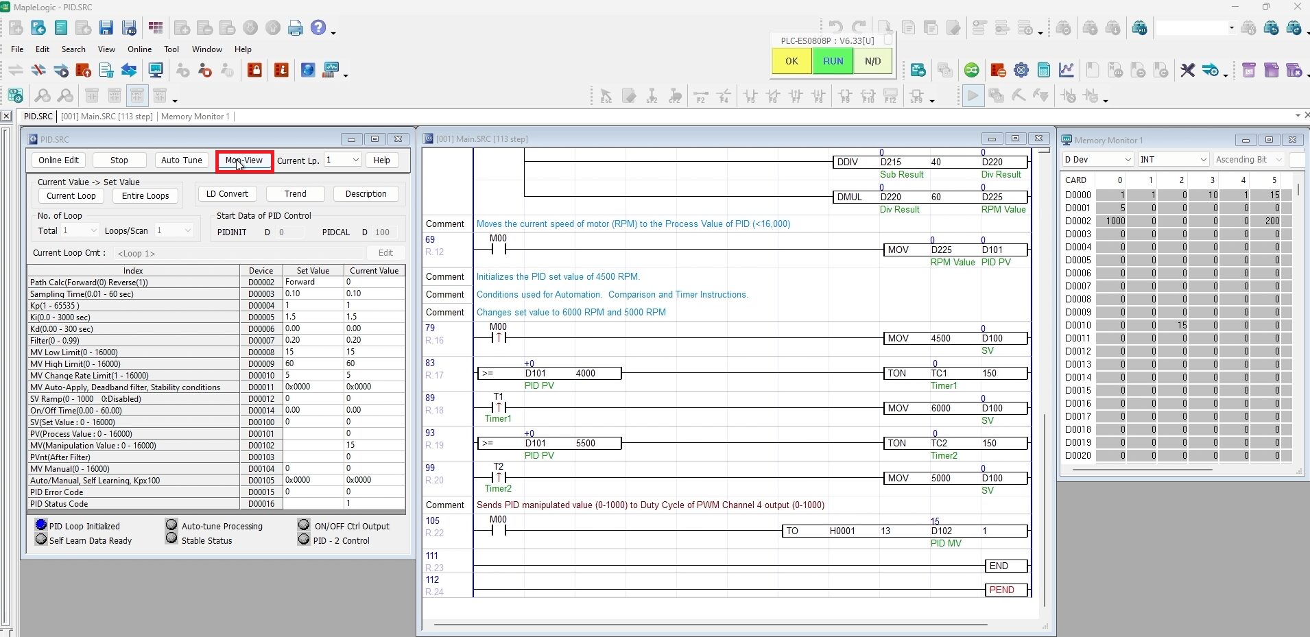
Click Mon-View to Monitor the initial values of the PID.
Click to highlight “M00“ and enter Shift + Enter to initiate the motor and enable the following rungs of logic:
- The HSC count
- Calculate the motor speed into RPM
- Move the RPM Value into the PID Process Value
- Send the PWM Duty Cycle into the PID Manipulative Value.
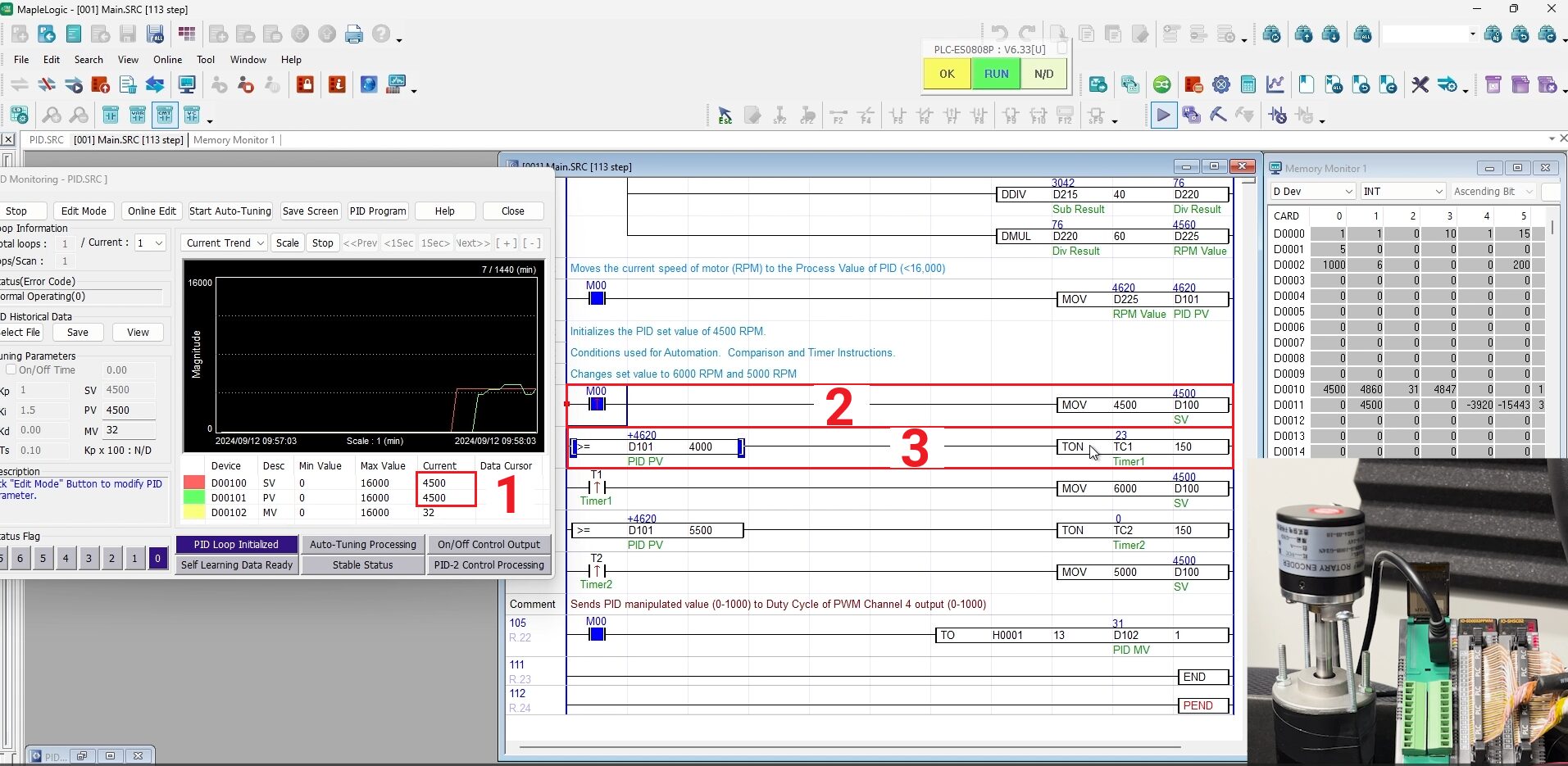
The Set Value is initially set to 4500 RPMs in the logic, therefore when the logic is enabled, the Process Value will begin to oscillate and attempt to reach that target value (set value).
1. When M00 is enabled, in the PID window, the Process Value will oscillate to reach the Set Value of 4500 RPM.
2. View the RPM value above the MOV function when M00 is enabled. The MOV function initially determines the Set Value of 4500 RPMs.
3. When the RPM value is greater than or equal to 4000 RPMs, a 15 second ON timer will be triggered.
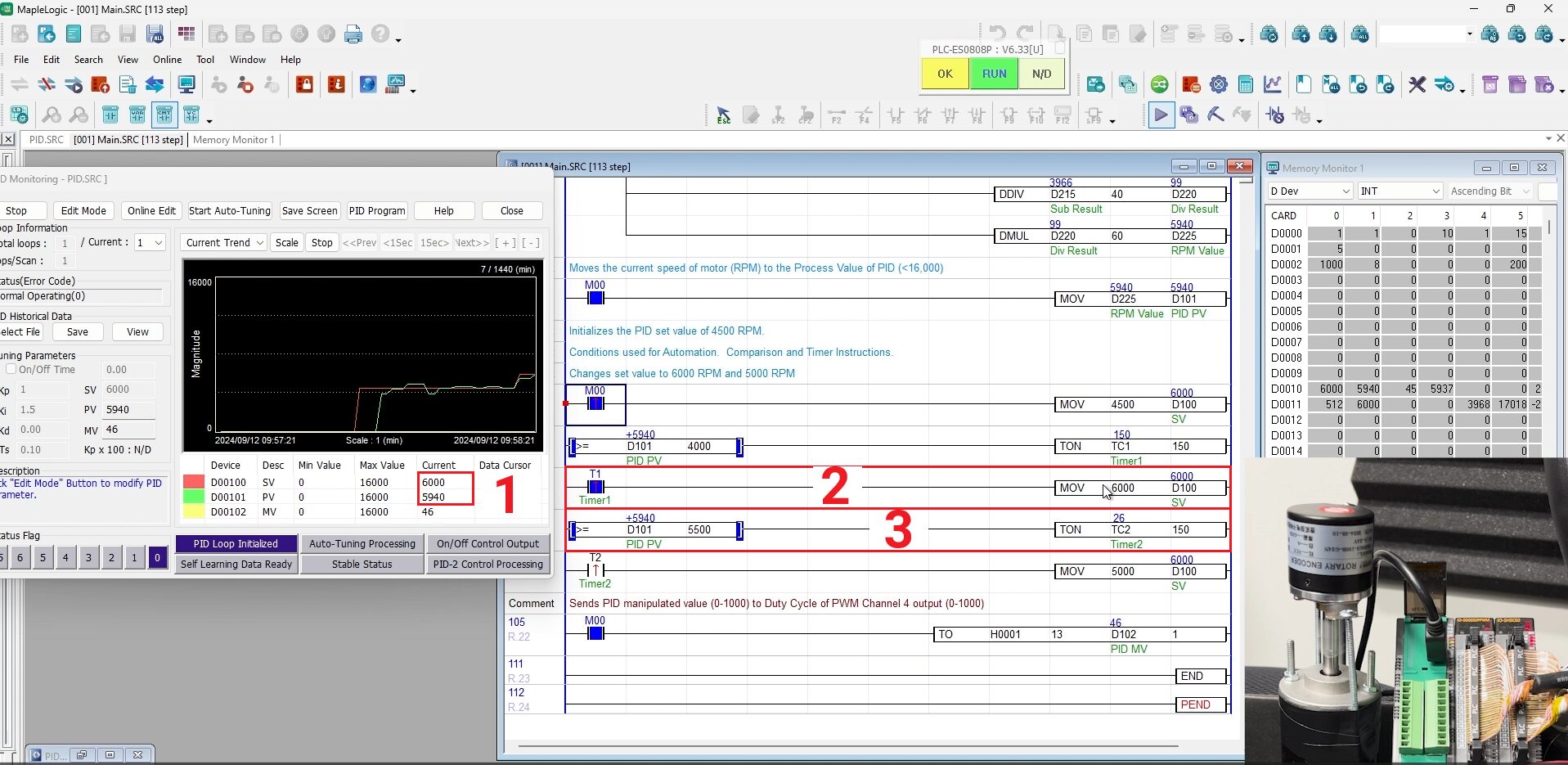
1. When the ON timer gets to 15 seconds, in the PID window, the Process Value will oscillate to reach the Set Value of 6000 RPMs according to the MOV function in step 2.
2. View the RPM value of 6000 RPMs above the MOV function.
3. When the RPM value is greater than or equal to 5500 RPMs, another 15 second ON timer will be triggered.
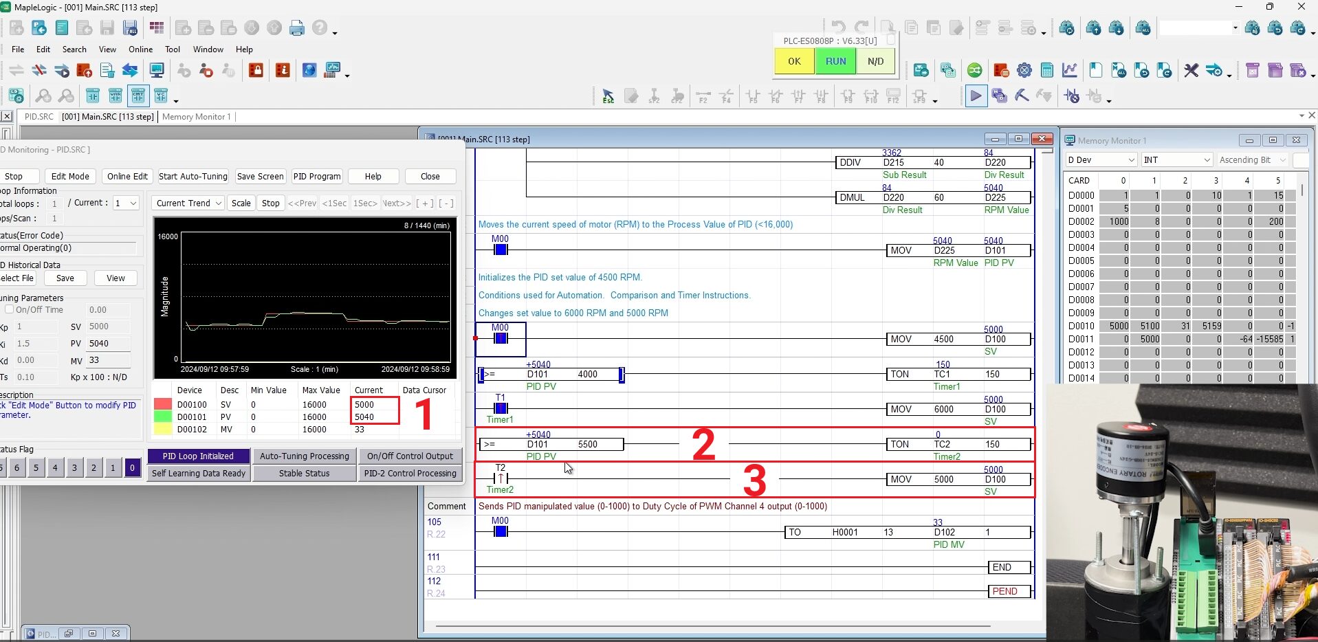
1. When the ON timer gets to 15 seconds, in the PID window, the Process Value will oscillate to reach the Set Value of 5000 RPMs according to the MOV function in step 2.
2. 15 second ON timer gets to 15 seconds and triggers the MOV function to move 5000 into the Process Value (D101).
3. View the RPM value of 5000 above the MOV function.
Sample Project
The project shown above was designed for the specific hardware mentioned at the beginning of the tutorial and is intended to provide you guidance when programming your unit. If you are using models other than the ones specified in this sample project, similar steps can be duplicated within your own project.
Download MapleLogic Sample Project
Resources & Documentation
Maple Systems PLC/MapleLogic Resources
- MapleLogic User Manual
- Maple Modular User Manual
- PID User Manual
- PWM Module User Manual (coming soon)
- High Speed Counter Module User Manual
- Digital Module User Manual (refer to the IO-SD0032PPWM)
About the Author
