Your cart is currently empty!
Applicable Model(s)
HMI5000 Series
cMT Series
Title
Video & Audio Features
Date
12/08/2022
Rev
05
P/N
0907-5101
Summary
Video: Live video can be viewed directly on select Maple Systems Advanced and cMT HMI products. Video input options are analog (composite) input, IP (Ethernet) cameras, and/or USB cameras. Video cannot be recorded, but still images may be captured from the live video. Images are captured via a bit trigger, making this feature ideal for capturing production or security events.
NOTE: Analog (composite) video input information is included in this tech note for legacy products but is no longer available on current HMI models.
Audio: Most Maple Systems HMI units have a transducer capable of sounding beeps. Select models have a mono speaker and a standard line-level output for driving amplified speakers via a standard 1/8-inch mini connector to play .wav files (review product specifications for model compatibility). This is useful for playing alert sounds when an alarm or event is triggered. Audio files are managed with the Sound Library.
NOTE: The line-level output may drive some non-amplified speakers, but the audio level will be quite low.
Web Streaming: Select models allow users to view a live video web stream on a remote computer from a USB video camera attached to the HMI. This is useful for monitoring a process or area of the manufacturing floor that is difficult to see from the operator’s position.
Media Playback: The Media Player object available on select models allows playback of media files on the HMI screen. The media file is stored on a USB flash drive or SD card connected to the HMI. This is ideal for displaying maintenance instruction videos to operators. The media player supports the following formats:
Advanced HMIs: avi, flv, mov, mp3, mp4, mpg/mpeg, wav, wmv
cMT HMIs: avi, flv, mkv, mov, mp3, mp4, mpeg4, wav
VNC Viewer: The VNC Viewer object allows you to connect to another device that has a VNC server and control it remotely. This includes the ability to connect to another HMI (except the cMT-SVR) and view and control it from the HMI screen.
PLC Web Browser: The PLC Web Browser is available on some cMT-X models only. It allows the HMI to connect to a web server on a PLC that can be used to configure the PLC and view PLC data.
Solution
Part 1 – Available Models
The following table illustrates which features each model supports.
| HMI Model | Audio Output | IP Camera | USB Camera | Web Streaming | Media Player (Video Playback) | VNC Viewer | PLC Web Viewer |
|---|---|---|---|---|---|---|---|
| cMT-SVR and SVRX | Y (Viewer) | N/A | N/A | Y | N/A | N/A | N/A |
| cMT Series | Selected Models1 | Y | Y | Y | Y | Y | N/A |
| cMT-X Series | Selected Models2 | Y | Y | Y | Y | Y | Selected Models3 |
| P and XL Series | N/A | Y | Y | Y | Y | Y | N/A |
| RMI5001 | Y (HDMI) | N/A | Y | Y | N/A | Y | N/A |
| L Series | N/A | N/A | N/A | N/A | N/A | Y | N/A |
| Basic Series | N/A | N/A | N/A | N/A | N/A | N/A | N/A |
2 cMT2158X – Line out/Mono speaker; cMT3092X – Mono speaker; cMT3161X – Mono speaker; cMT3162X – Mono speaker; cMT-FHDX-220, cMT-FHDX-820 – HDMI audio out
3 cMT3072X/cMT3072XH/cMT3092X/cMT3152X/ cMT3162X support PLC Web Browser
P and XL Series: HMI5070P, HMI5121P, HMI5150P, HMI5097NXL, HMI5097DXL, HMI5020XL, HMI5121XL, HMI5150XL
L Series: HMI5043L, HMI5043LB, HMI5043DL, HMI5070NL, HMI5070L, HMI5070LB, HMI5070R, HMI5070DL, HMI5071L, HMI5100L, HMI5102L, HMI5103L
Basic Series: HMI5040BN, HMI5040B, HMI5070BN, HMI5070B, HMI5100BN, HMI5100B
cMT Series: cMT3071, cMT3072, cMT3090, CMT3103, cMT3151, cMT-HDM, cMT-FHD
cMT-X Series: cMT2078X, cMT2158X, cMT3072X, cMT3072XH, cMT3092X, cMT3152X, cMT3161X, cMT3162X, cMT-FHDX-220, cMT-FHDX-820
Part 2 – Creating the Video In Object
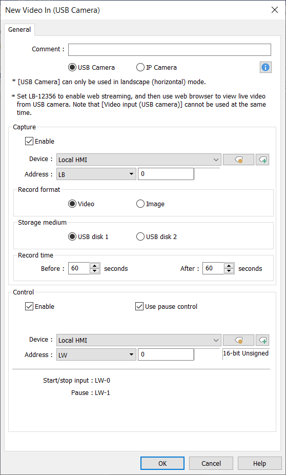
Analog, USB, and IP video have similar configurations. From the Objects menu, select Video In, or click the icon on the Object2 toolbar. The Video In object configuration dialog is displayed.
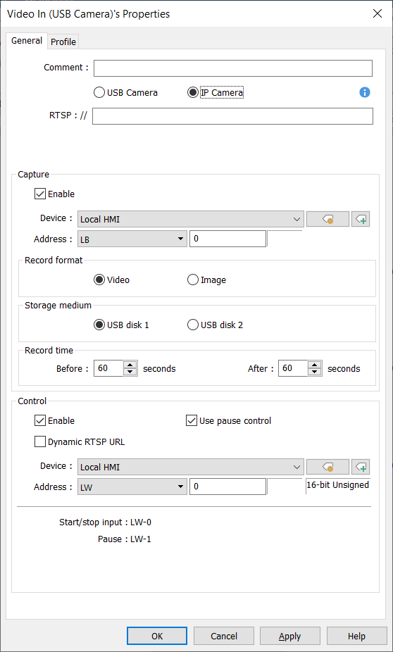
The General tab configures how the object will function.
Note: All options are shown below, but not all options are available for all products.

USB Camera / IP Camera – The select HMI will show whichever video input sources are available for that model.
Encode Format (Composite Input Models Only) – The Video Input has 2 separate channels. Both channels are set to the same format (NTSC or PAL). The two channels cannot be displayed simultaneously on the same window, but the display can be switched between channels.
RTSP / Streaming over TCP (IP Camera Input Models Only) – Only IP Cameras that use the ONVIF (Open Network Video Interface Forum) standard and do not require software to be installed are supported.
The RTSP:// streaming URL is required for the software to display the video stream. Check your camera’s user manual to determine the URL format. Streaming over TCP – Select this check box to stream video over TCP.

Capture Address
When Use Capture Function is checked, the HMI can capture images from the live video. When the specified bit toggles from 0 to 1 (the trigger event), an image is saved to the specified Storage Medium. This could be used to capture an image when an input to the PLC turns on. Image filenames are based on the current date and time in the HMI clock, and are of the format yyyymmddhhmmss. Images captured from the composite video inputs are Jpeg images, and have the extension JPG. Images captured from the USB video or IP Camera input are Portable Network Graphics images, and have the extension PNG.
Storage Medium
Specify whether images are to be stored to the SD card or USB disk. If USB Camera is selected as the source, only the SD card is available. Images from the analog video input are saved to the folder VIP1 (channel 1) or VIP2 (channel 2). Images from the USB video input are saved to the folder USB_CAMERA. Use the Picture Viewer object in the HMI software to display captured images directly on the HMI. An FTP client can be used to retrieve the images from the specified storage medium. Refer to Maple Systems’ Technical Note 0907-5090 for details.
Record Time (Composite Input Models Only)
With the Composite Input Models, images captured from the analog video (Video In, channel 1 or 2) bracket the trigger event. The Graphic HMI retains 10 seconds of prior video, with one image captured per second. The Record Time settings specify how many images are captured before and after the trigger event. The Before and After settings each have a maximum of ten seconds. Therefore, a maximum of 21 images can be captured:
- 10 images before the trigger event occurs
- 1 image when the trigger event occurs
(the filename of this image will contain the @ symbol) - 10 images after the trigger event occurs
