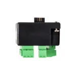
I/O Module
There is no direct replacement for this item. See HMC3-M0808Y0401T-V2 as a possible upgrade option.
Can customers use the M0808Y0401T-V2 module to replace their M0808P0401T module?
- Yes, if they were using 2 digital outputs or less on their M0808P0401T module. However, the customer would need to convert their application to the Y-type module. The converting process includes exporting and importing logic/screens to a new project and then allocating to the correct module. The process is described in Tech Note #7020 and is only valid for conversion using the same HMC series, if going from HMC4 – HMC2, only exporting and importing logic is possible.
- No, if they are using more than 2 digital outputs of the P-type module. They would need an additional module that has more digital sourcing outputs.
This is a Legacy product and is no longer available for purchase. Please review the information on this page and call (425)-745-3229 or email [email protected] if you have further questions.
Share the product:
Compare to Similar Models
Compare HMC3-M0808P0401T with 1 other product


|
Filters |
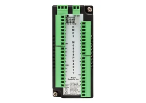
I/O Module HMC3-M0808P0401T Price Not Available (N/A)
|
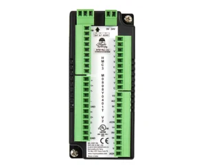
I/O Module | 8 Bi-Directional Digital Inputs, 8 Digital Outputs, 4 Analog Inputs, 1 Analog Output, Thermo/RTD HMC3-M0808Y0401T-V2 $295
|
|---|---|---|
| Loading product data… | ||
There is no direct replacement for this item. See HMC3-M0808Y0401T-V2 as a possible upgrade option.
Can customers use the M0808Y0401T-V2 module to replace their M0808P0401T module?
- Yes, if they were using 2 digital outputs or less on their M0808P0401T module. However, the customer would need to convert their application to the Y-type module. The converting process includes exporting and importing logic/screens to a new project and then allocating to the correct module. The process is described in Tech Note #7020 and is only valid for conversion using the same HMC series, if going from HMC4 – HMC2, only exporting and importing logic is possible.
- No, if they are using more than 2 digital outputs of the P-type module. They would need an additional module that has more digital sourcing outputs.
What happens if I delete the auto-generated tags for the IO modules in MAPware7000? How do I get them back?
In IEC mode, tags cannot be given local addresses by the user. If you delete auto-generated tags and want to get them back, open the IO configuration wizard (IO Allocation > Expansion) and reconfigure the module. Just click the dropdown menu and select the configuration that you want, even if it is already set to that configuration. Click “Confirm” and close the wizard. The program should pause briefly as the auto-generated tags are created again. Check in the tag library for the newly generated tags.Why is my I/O module not working properly?
Most I/O modules require a separate +24VDC power supply connection. See the appropriate Series I/O Module Guide to locate this connection on a specific I/O module.Analog inputs and outputs require writing a value to a corresponding configuration register to program the I/O for 4-20 mA, 0-10V, RTD, etc. Although there is a Configuration option when adding an I/O module in the Expansion IO Allocation window, if the I/O module isn’t operating properly, we recommend using Power-On Tasks to write the appropriate values to the configuration registers at startup.
Also, it may be necessary to update the firmware in the I/O module. See Tech Note 7008, “Update HMC7000 Series Expansion Module Firmware,” for instructions on how to do this.
Do the Maple Systems HMI+PLCs (HMC) support High-Speed Counters (HSC)?
Yes. Our HMI+PLCs (HMC) support High-Speed Counters in MAPware-7000. See the specific Series IO Module guide for more information on which IO modules support High-Speed Counters (HSC) and what registers are used for configuration. Most supported IO modules offer 2 or 4 high speed inputs. Both quadrature and standard HSCs are supported. When using HSCs, different product lines have different maximum frequencies ranging from 10 kHz to 200 kHz.Do the Maple Systems HMI+PLCs (HMC) support Pulse Width Modulation (PWM)?
Yes. Our HMI+PLCs (HMC) support Pulse Width Modulation in MAPware-7000. See the specific Series IO Module guide for more information specifics on which IO modules support Pulse Width Modulation (PWM) and what registers are used for configuration. Four modes of PWM are supported for most IO modules; Normal, Clockwise/Counter-Clockwise (CW/CCW), Pulse/Direction, and Trapezoidal (Fixed Pulse). When using PWM outputs, different product lines have different maximum frequencies ranging from 1 kHz to 200 kHz. Tech Note 7009, “Pulse Width Modulation”, describes each of the four types of PWM output, and then lists which registers to configure, how to configure those registers, and the minimum and maximum ranges of each register. Review the IO module specification sheets to ensure PWM is available.What is the difference between NPN and PNP?
NPN (Sinking) and PNP (Sourcing) are two types of transistors used for digital outputs. The terms Sinking and Sourcing refer to current flow with respect to the terminal pin on the IO card. A device is called sinking if current flows into the terminal, and is called sourcing if current flows out of the terminal.-
- PNP transistor outputs are called “sourcing outputs” because they source current from the output to the load.
- NPN transistor outputs are called “sinking outputs” because they sink current from the load into the output.
The question of sinking vs. sourcing and NPN vs. PNP causes confusion throughout the controls industry. Often engineers working on different parts of a system will not communicate the chosen configuration. These errors will inevitably be discovered, the question is when and at what cost?
This paper will define these terms and what they mean with respect to digital input and digital output circuits used in industrial control systems. Then we will explore how these components are used and some of the issues to be aware of when selecting components for a system.
Definition of Terms
The terms NPN and PNP are commonly used as synonyms for sinking and sourcing respectively. This is a reasonable assumption but strictly speaking they refer to different concepts.
The terms NPN and PNP refer to how a transistor is constructed. A transistor is a three layer sandwich of two different types of material, the two outside layers are the same and the middle layer is different. The magic of the transistor is that the layer in the middle can be used to control the flow of current between the outside layers. The two types of material that can be used to build a transistor are n-type and p-type. Thus, there are two possible types of transistor: NPN and PNP. The practical difference between these two transistor types is in how current flows through the circuit. In a bipolar junction transistor (BJT) the control leg, the middle of the sandwich, is called the base. The other two connection points are called the collector and the emitter. In a PNP transistor a small current flowing from the emitter into the base causes a larger current to flow from the emitter to the collector.

On a circuit diagram this is indicated by a small arrow on the emitter Pointing iN to the base.

In an NPN transistor a small current flowing from the base to the emitter causes a larger current to flow from the collector to the emitter.

On a circuit diagram this is indicated by a small arrow on the emitter pointing away from the base (or Not Pointing iN to the base).

Note that in a PNP transistor current flows from the emitter to the collector. While for an NPN transistor current flows from the collector to the emitter.
So, how does the choice of an NPN or PNP transistor relate to the issue of sinking vs sourcing? The terms sink and source are used to indicate which way current is flowing with respect to some reference point. In the controls world, the reference point is typically a screw terminal on an output card. If current flows into the screw terminal the device is said to sink current. If current flows out of the screw terminal it is said to source current. The connection between sinking vs. sourcing and NPN vs. PNP has to do with which type of transistor is used to create the circuit and where it is placed relative to the load being controlled.
In a PNP (BJT) transistor, to get current to flow from the emitter to the collector, a small control current must flow from the emitter into the base. Thus the base must be held at a lower voltage than the emitter. If the load were connected between the power supply and the emitter the voltage at the emitter will be pulled down as the transistor begins to conduct. That is when no current is flowing through the load there is no voltage drop across the load. As current begins to flow the voltage drop across the load is given by Ohm’s law: VL = IRL. This voltage drop makes it harder to maintain a voltage at the base that is lower than the voltage at the emitter.
Thus for a PNP transistor the load is usually connected to the negative side of the transistor, which is the collector in the case of a PNP transistor. In a digital output the load is connected to the output pin on the IO module, so current flows out of the pin and into the load, hence this type of output is said to source current.
In an NPN transistor current must flow from the base into the emitter to activate the transistor. This requires that the base is held at a higher voltage than the emitter. If the load were connected between the emitter and 0V this would become harder to do as the transistor began to conduct current and the voltage drop across the load begins to rise. So, when using an NPN transistor the load is placed before the transistor, between the power supply and the collector. In an output module the load is connected to the output pin so current flows from the load into the terminal and this type of output is called a sinking output.
For our purposes we will follow convention and assume NPN = Sinking and PNP = Sourcing.
Putting Things Together
Let’s explore the different configurations possible using NPN / Sinking and PNP / Sourcing, inputs and outputs and some of the issues involved. In a typical digital control circuit there are three components that need to be connected together, in the correct order, to make the circuit work. These are; the power supply, the output and the input.
Since we are discussing DC circuits the power supply will have positive and negative connections, typically 24VDC and a 0VDC.

The output could be several different types of devices; a switch, a relay contact, or a sinking or sourcing transistor output. A transistor output will be either a sinking (NPN) output that can only be used after the load (the load being the input in this case). Or, it will be a sourcing (PNP) output that can only be used before the load.

All of the outputs on the IO card will have their negative terminals tied together inside of the card and connected to a common pin. This common pin can only be connected to 0V in the case of sinking (NPN) outputs or only to 24V in the case of sourcing (PNP) outputs:

Relays and switches are more flexible, they can be wired to source or sink current.
The final piece of the puzzle is the input. For this discussion, the input is modeled as an LED and current limiting resistor.

This is a simplification of an optically isolated input. To turn the input on you allow current to flow through the diode so that it emits light. That light activates a photo transistor, which in turn sets the input bit to true. With this type of input circuit there really isn’t a good reason why it can’t be connected directly to 24VDC on the power supply when using a sinking (NPN) output to drive it. Or, directly to 0v on the power supply, after the output, when using a sourcing (PNP) output. As long as sufficient current is flowing through the diode it will turn the input on.
The problem with this type of input is that there are several inputs on one IO module and they all have one side tied to a common terminal pin. A sourcing only input will have the 24VDC connection made internally. And a sinking input will have the 0V connection made internally.

If you put the switch (output) on the common pin you would switch all of the inputs at once. If you try to reverse the polarity of the power supply the diode will not let current flow backward through the input, regardless of the state of the output. One way to solve this problem is to use two diodes for each input. These are placed in parallel facing opposite directions.

With this configuration, if the power supply is reversed one of the diodes will continue to function. Indeed, many manufacturers (including Maple Systems) supply bidirectional inputs that can function in either direction. Note that the power supply will be connected to all of the inputs sharing a common terminal. As a consequence the entire module can be used in sinking or sourcing configuration but cannot have a mix of sinking and sourcing inputs using the same common pin.

There are good design reasons to prefer a sourcing output with sinking input in one situation and a sourcing output and sinking input in another situation.
When purchasing components for a system it is wise to maintain the most flexibility possible. For example, when deciding on an output card or sensor that could be used in many different situations it is a good idea to use relays with Normally Closed and Normally Open contacts. These can be wired to sink or source depending on the situation. That said, there are reasons to use transistor outputs that often trump the need for flexibility. Chief among these are; speed, cost and space requirements.
When sourcing inputs use bidirectional inputs whenever possible. This will maintain the most flexibility possible. It really does not increase the cost of the Input card at all, so unless there is a specific reason to get a sourcing only or sinking only input bidirectional is the way to go.
So what happens, when despite the best intentions, a need arises to connect a sinking output to a sinking only input or a sourcing output to sourcing only input? For example, a systems integrator always buys sinking only inputs but a particular sensor manufacturer only has sensors with sinking outputs. No one caught the conflict in the design phase and now it’s time to commission the system. What can be done? It is possible to use a resistor to convert a sinking output into a sourcing output, or a sourcing output into a sinking one. In the case of a sinking output simply use the resistor as the load instead of the input:

When the output is off, current only flows through the input, turning it on. When the output is on, current flows through the transistor, pulling the voltage at the low side of the external resistor down to nearly 0V and turning the input off. The transistor turns off the input by steeling all the available current.
To turn a sourcing output into a sinking output again, the resistor replaces the input as the load. This time the resistor is placed between the output pin and zero volts on the power supply.

When the output is off, current can only flow through the input; turning it on. When the output is on a larger amount of current flows through the transistor to the external resistor, bringing the high side of the resistor to nearly the power supply voltage, and turning the input off.
In both cases the resistor value must be selected so that, when the output is off, enough current flows through the external resistor to turn the input on but, when the output is on, the output can sink or source enough current through the resistor to lower or raise the voltage enough to turn the input off. Inputs typically have very high impedance so this is not a problem.
This can be done in a pinch, but there will be a discrete resistor floating around between screw terminals somewhere. This makes for a less tidy installation and will probably cause confusion when someone tries to upgrade or maintain the system, so it’s generally not recommended. Better to plan ahead and use components with as much flexibility as possible.
How do I update the firmware in my Maple Systems HMC Module?
When downloading a new project to an HMC7000 Series, or after upgrading MAPware-7000, it may be necessary to upgrade the firmware of an expansion module. To update the firmware in an HMI + PLC or PLC Expansion Module:- Open a project in MAPware-7000 and connect the HMC to the computer using either a USB or serial configuration cable.
- Click the View menu at the top of MAPware-7000 and select Device Information.
- In the Device Information window, select USB or Serial, depending on your connection method, then click View.
- The Device Information View window shows the HMC model in Slot No. 0 and the connected expansion modules in their associated Slot No.
- Click the Upgrade button under the Upgrade Firmware column to see if the associated expansion module has the current firmware installed.
- If the device has an older version of firmware, installation of the current firmware will begin automatically.
- Once the firmware has been upgraded in all the expansion modules, click the Close button to complete the process.
Software Downloads & Upgrades
Manuals & Guides
- HMC Series Installation Guide
- MAPware-7000 Programming Manual
- MAPware-7000 Ladder Logic Guide
- Mapware-7000 Getting Started Guide
- HMC3000 I/O Module Guide
- HMC7000 I/O Module Guide
- MAPware-7000 IEC61131 Programming Guide
Videos
- Part 1: Introduction and Installation
- Part 2: Creating a Native Ladder Project
- Part 3: Adding and Initializing Tags
- Part 4: Adding Logic
- Part 5: Creating an HMI Screen
- Part 6: Duplicationg an HMI Screen
- Part 7: Downloading and Testing the Project
- Part 8: Creating an IEC Project
- Part 9: Creating a UDFB
- Part 10: Adding a Structure Text UDFB
- Part 11: Adding Power Up and Main Routine Logic
- Part 12: Creating Screen Objects
- Part 13: Downloading the Project and Online Monitoring
Sample Projects