Maple Systems Web HMIs can connect to a web server hosted by a microcontroller such as an Arduino. In this example, the Web HMI’s integrated browser is used to control GPIO outputs on an Arduino microcontroller with an Arduino Ethernet Shield 2.
This article walks you through the process of connecting a Web HMI to an Arduino web server. It also explains how to program the Arduino to host a web server with custom code. At the end of the article, you will find wiring diagrams and program files to help you recreate the setup.
Connecting the Web HMI
The WP4000 series Web HMI provides a practical way to interact with an Arduino web server. It is easy to configure and deploy, and its bright physical touchscreen makes it easy to view and control web applications.
Connect the Web HMI to the Arduino Web Server
Configure the Web HMI browser to open the Arduino web server by entering the server IP address in the Web Apps settings.
Instructions: Connect the Web HMI to the Arduino Web Server
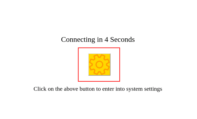
Open the Configuration Screen
Power on the WP4000 Web HMI and allow it to boot → Watch for the settings icon and countdown timer → Tap the settings icon before the timer expires.
Open the Web Apps Menu
From the main settings menu → Navigate to the Web Apps page → Enter the device password if prompted.

Enter the Arduino IP Address
In the URL entry screen → Enter the Arduino IP address assigned by DHCP → In this example, use 192.168.150.187.

Save the Web App Configuration
After entering the Arduino IP address → Tap Save to store the configuration.
Reboot and Launch the Web Interface
Allow the HMI to reboot → Let the settings timer expire → The Web HMI will load the index.htm file stored on the Arduino Ethernet Shield 2 SD card.

Controlling the Arduino
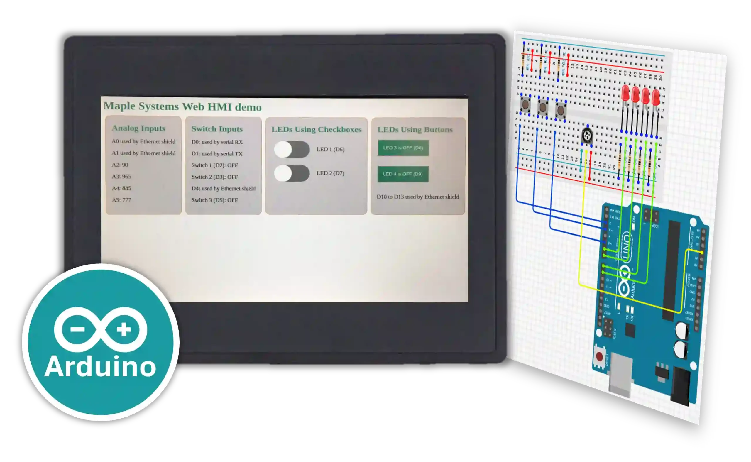
The web interface lets users control LED lights connected to digital GPIO pins on the Arduino from the Web HMI.

The Arduino can also report digital GPIO input states to the Web HMI.

In addition, the Arduino can report analog GPIO input values in real time as they change.

The Arduino platform is a versatile tool for learning, prototyping, and developing small-scale applications. Although this demo focuses on LED lights, buttons, and a potentiometer, you can apply the same concepts to many other hardware devices and data sources, such as sensors or control relays.
Assembling the Hardware
The Web HMI
For this demonstration, we use the 7-inch resistive touch-screen Web HMI, the WP4070A, to connect to the web server hosted by the Arduino. The unit is straightforward to install and deploy, so it requires very little setup effort.
Once connected, the Web HMI touchscreen provides a simple interface for visualizing and controlling the Arduino GPIO.
This demonstration uses a small group of off-the-shelf parts together with the Maple Systems Web HMI. The selected hardware requires no soldering and can be assembled at an office desk.

Arduino Development Board
An official Arduino MEGA 2560 R3 runs the web server program. This development board uses the ATMEGA2560 microcontroller and provides the GPIO needed to control a variety of devices. In this demo, it controls LED lights and reads button inputs.
Ethernet Module
Because the Arduino MEGA does not include an Ethernet interface, an additional daughterboard, or shield, is installed on top of the base board. In this project, the selected module is the Arduino Ethernet Shield 2.
The Ethernet Shield 2 plugs into the Arduino GPIO pins, fits neatly above the controller board, and provides additional ports along with pass-through GPIO pins. It also includes a Micro SD card slot, which stores files accessed by the Arduino program. In this demonstration, the SD card stores the HTML file used to serve the web page to the Web HMI.
Test Circuit
Alongside the Arduino board, a simple circuit was assembled on a solderless breadboard to provide several LED lights, buttons, and a potentiometer. These components connect to the GPIO pins available on the Arduino.

The Arduino web server program sends signals to these components. The web UI then lets users control the LED lights and view input data from the buttons and potentiometer knob.
Programming the Arduino
All Arduino programming for this project, including writing the code, downloading the program, and monitoring debug output, is done in the Arduino IDE. You can open the code provided at the end of this article in Arduino IDE and download it to another Arduino board to recreate the demo.
Code Explanation
The program performs several core tasks. It sets up GPIO pins for the Arduino, initializes the Ethernet interface and connects it to the network, and serves an HTML file to the Web HMI.
Initializing the Ethernet Shield
The SPI, Ethernet, and SD libraries are required to use the Arduino Ethernet Shield 2 network interface and SD card slot. You must also define basic network parameters such as the device MAC address and IP address information.
#include <SPI.h>
#include <Ethernet.h>
#include <SD.h>
...
// Initialize MAC address of Ethernet Module in use. This must be changed if deploying on a different device!
byte mac[] = {0xA8, 0x61, 0x0A, 0xAE, 0x09, 0xEB};

// Initialize default network configurations should DHCP configuration fail
byte staticIP[] =         {192, 168, 5, 20};
byte staticGateway[] =    {192, 168, 5, 1};
byte staticDNS[] =        {8, 8, 8, 8};
byte staticSubnetMask[] = {255, 255, 255, 0};Code language: PHP (php)
To configure the Ethernet interface with network settings, call the Ethernet.begin() method.
Ethernet.begin(mac, staticIP, staticDNS, staticGateway, staticSubnetMask);Code language: CSS (css)The full program available at the end of this article first uses Ethernet.begin() to request an IP address over DHCP, then falls back to the static values shown above if needed.
Setting Up the SD Card
The server must provide an HTML/CSS file to any client web browser that connects to it. In this project, an index.htm file is loaded onto an SD card, which is then installed in the Ethernet Shield 2. The HTML and CSS code on that card define the control interface shown on the Web HMI and the formatted data exchanged with the Arduino web server.

The program loads the file by using SD.begin() and SD.exists(), along with logic that reports an error if the file cannot be found on the card.
// Initialize SD card with web server files
Serial.println("Initializing SD card...");
if (!SD.begin(4)) {
      Serial.println("Error: SD card initialization failed!");
      return; // Init failed
}
Serial.println("SD card initialized successfully.");
// check for index.htm file
if (!SD.exists("index.htm")) {
      Serial.println("Error: Can't find index.htm file!");
      return; // Can't find index file
}
Serial.println("Found index.htm file.");Code language: JavaScript (javascript)
Later, the server provides the HTML file to a client browser by using the SD.open() method.
...

// Send web page file stored on the SD card
webFile = SD.open("index.htm"); // open web page file
if (webFile) {
  while(webFile.available()) {
    client.write(webFile.read()); // send web page to client
    }
webFile.close();
}

...Code language: JavaScript (javascript)
Controlling GPIO Pins
The web UI controls and monitors the GPIO pins. In this demo, it performs the following tasks:
- Turns 4 LEDs on and off
- Registers when any of 3 buttons are pressed
- Reads an analog value from a potentiometer dial
The Arduino program must initialize the GPIO pins as either inputs or outputs. This is done with the pinMode() method.
// Initialize GPIO pins for hardware controlled by web server
// Pins 2, 3, and 5 for button inputs
pinMode(2, INPUT);
pinMode(3, INPUT);
pinMode(5, INPUT);

// Pins 6-9 for LED outputs
pinMode(6, OUTPUT);
pinMode(7, OUTPUT);
pinMode(8, OUTPUT);
pinMode(9, OUTPUT);Code language: JavaScript (javascript)
The analog pin used in the test circuit, pin A2, is input-only, so it does not need any additional configuration.
By using digitalWrite() and digitalRead(), the program can check the button states on pins 2, 3, and 5 and control the LEDs on pins 6 through 9.
// Read button states
for (count = 0; count < 3; count++) {
      cl.print("<switch>");
      if (digitalRead(sw_arr[count])) {
            cl.print("ON");
      }
      else {
            cl.print("OFF");
      }
      cl.println("</switch>");
}

...

for (count = 0; count < 4; count++) {
   pin = count + 6; // Consecutive LED pin offset for pins 6-9

   // Unique HTML text for turning individual LEDs on or off
   on_string = "LED" + String(count + 1) + "=1";
   off_string = "LED" + String(count + 1) + "=0";

   // Convert strings to char arrays for use with StrContains()
   on_string.toCharArray(on_message, 7);
   off_string.toCharArray(off_message, 7);

   if (StrContains(HTTP_req, on_message)) {
      LED_state[count] = 1; // Save LED state as ON
      digitalWrite(pin, HIGH);
   }
   else if (StrContains(HTTP_req, off_message)) {
      LED_state[count] = 0; // Save LED state as OFF
      digitalWrite(pin, LOW);
   }
}Code language: PHP (php)
The program reads the analog value on pin A2 by using the analogRead() method.
// Read analog inputs
for (count = 2; count <= 5; count++) { // A2 to A5
     analog_val = analogRead(count);

...Code language: JavaScript (javascript)
Hosting the Web Server on the Ethernet Interface
After the program assigns an IP address to the Ethernet interface, it can host the web server and listen for clients over Ethernet. Because the GPIO pins were initialized earlier, the user can control the test circuit from the hosted web server.
The EthernetServer and EthernetClient classes, provided by the Ethernet Shield libraries, let the program define objects for the hosted server and the connected client. The following statements host a server on the default HTTP port, TCP port 80, and listen for client connections.
// Configure web server
EthernetServer server(80); // Web server hosted on port 80

...

// Watch for connection to web server
EthernetClient client = server.available();

...Code language: JavaScript (javascript)
Finally, the main program loop ties all of these functions together. It monitors the network connection, maintains the DHCP lease when needed, listens for client requests, and returns either the HTML page or XML data.
void loop() {
   // Continuously check if ethernet module is connected to a network
   CheckEthernetConnection();

   // Continuously maintain DHCP lease if it was configured successfully
   if (using_DHCP) {
      MaintainDHCPLease();
   }

   // Watch for connection to web server
   EthernetClient client = server.available();

   // When client connects, begin repeatedly polling entered data
   if (client) {
         boolean currentLineIsBlank = true;
         while (client.connected()) {
               if (client.available()) {    // If client data is available to be read, read 1 byte (character) from the client
                     char c = client.read();
                     // Limit the size of the stored HTTP request from the client
                     // Buffer first part of the request in an array (string)
                     // Leave last element in array as 0 to null terminate string (REQ_BUF_SZ - 1)
                     if (req_index < (REQ_BUF_SZ - 1)) {
                           HTTP_req[req_index] = c;               // Store HTTP request character
                           req_index++;
                     }
                     // The last line of the client request will always be blank and end with n
                     // Only respond to the client after the last line is received
                     if (c == 'n' && currentLineIsBlank) {
                           // Send a standard HTTP response header
                           client.println("HTTP/1.1 200 OK");
                           // Send the remainder of the header, which differs depending on whether
                           // a web page or XML file is requested
                           // For an Ajax request, send the XML file:
                           if (StrContains(HTTP_req, "ajax_inputs")) {
                                 client.println("Content-Type: text/xml");
                                 client.println("Connection: keep-alive");
                                 client.println();
                                 SetLEDs();
                                 // Send XML file containing input data
                                 XML_response(client);
                           }
                           else {   // For a web page request, send the HTML file"
                                 client.println("Content-Type: text/html");
                                 client.println("Connection: keep-alive");
                                 client.println();
                                 // Send web page file stored on the SD card
                                 webFile = SD.open("index.htm");            // open web page file
                                 if (webFile) {
                                       while(webFile.available()) {
                                             client.write(webFile.read()); // send web page to client
                                       }
                                       webFile.close();
                                 }
                           }
                           // Output any HTTP requests on the serial port
                           Serial.print(HTTP_req);
                           // Reset the buffer index and all buffer elements to 0
                           req_index = 0;
                           StrClear(HTTP_req, REQ_BUF_SZ);
                           break;
                     }
                     // Every line of text received from the client will end with rn
                     if (c == 'n') {
                           // last character on line of received text
                           // starting new line with next character read
                           currentLineIsBlank = true;
                     }
                     else if (c != 'r') {
                           // a text character was received from client
                           currentLineIsBlank = false;
                     }
               } // end if (client.available())
         } // end while (client.connected())
         delay(1);         // give the web browser time to receive the data
         client.stop(); // close the connection
   } // end if (client)
}Code language: PHP (php)
Running the Program
The program starts automatically after it is downloaded to the Arduino. It also initializes the serial console, which lets you view messages from the Arduino in the Arduino IDE. This output is useful for confirming details such as the IP address assigned to the device.

Building the Test Circuit
To pair with the Arduino program, we built a small circuit that connects LEDs, buttons, and a potentiometer knob to the appropriate GPIO pins.

- Pins 2, 3, and 5 connect to switch outputs with pull-up resistors, so the pins are pulled HIGH when the buttons are pressed.
- Pins 6 through 9 connect to the positive leads of 4 LEDs. When the Arduino sets these pins HIGH, the LEDs turn on.
- Pin A2 connects to the wiper lead of a potentiometer knob. As the knob changes the resistance, the voltage at pin A2 changes, which changes the analog value read by the Arduino.
Final Thoughts
Maple Systems WP4000 series Web HMIs are flexible devices that can use an integrated web browser in many different applications. For another example, check out our previous article on using a Web HMI with noVNC for remote desktop access to a Raspberry Pi.
Please visit our product pages for more information about the HTML5 Web HMI series, or contact us to see whether Maple hardware is the right fit for your application.
Resources & Documentation
The following guides and documentation are specific to the hardware used in this integration tutorial and will help you with setup, configuration, and programming:
Looking for additional learning resources? Explore our library of tutorials, example projects, and software tools to help you get the most out of your system:
Also, browse our Support Center for a complete list of installation guides, FAQs, and additional technical documentation.
About the Author
Trusted source for industrial automation & control solutions
Follow Maple Systems:
Share:


