A practical industrial automation scenario connects a Maple Systems HMI to an AutomationDirect PLC in a packaging cell or conveyor line. The PLC handles real-time machine control. The HMI provides visualization, data tracking, and system connectivity.
For example, a CLICK PLC can manage motors, sensors, safety interlocks, cycle logic, and fault handling. The Maple HMI provides operator screens for start and stop control, recipe management, alarm displays, and trend visualization.

In addition, the HMI can log production data such as part counts, uptime, downtime, and fault history, giving operators and supervisors clear insight into performance without modifying the core PLC logic.
Software Required
- EBPro (Required software for any Maple Systems HMI)
- CLICK Programming Software
Hardware Required
- Any Maple Systems HMI (cMT3072X2 is used in this example)
- Automation Direct PLC (C0-10DD2E-D is used in this example)
Network Diagram

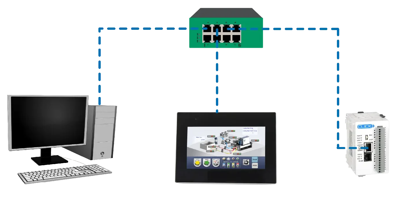
The diagram above illustrates a small local Ethernet network where a PC, a 7-inch HMI, and a CLICK PLC connect through a central network switch. Each device uses an IP address within the same subnet: the PC uses 192.168.255.75, the HMI uses 192.168.255.29, and the PLC uses 192.168.255.28.
The HMI and PLC communicate using the Modbus TCP/IP protocol. The HMI typically acts as the Modbus client (master), while the PLC acts as the server (slave). This setup allows the HMI to read data from and write data to the PLC to monitor and control the automation system. The PC only serves to download the project to the HMI during setup using EBPro programming software.
PLC Configuration
This section covers how to start a new CLICK project, select the correct PLC model, and set up required password protection for secure access.
CLICK Programming Software Setup
Follow the step-by-step guide on getting started with the CLICK Programming Software
Instructions: CLICK Programming Software Setup
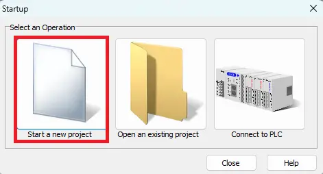
Starting a New Project
– Choose Start a new project
Choosing the PLC
– Select the CPU Category (Ethernet Basic for this example)
– Select the CPU Type (C0-10DD2E-D for this example)
– Click OK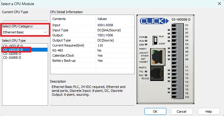
User Account Setup
– Click Password Setting
– Enter a New Password, and confirm that password
– Click OK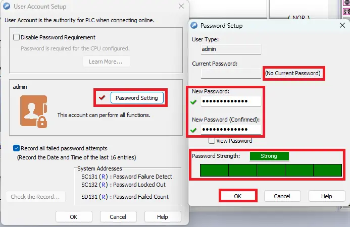
PLC Logic Build
This section provides a simple example of how to build basic ladder logic in CLICK by adding contacts and using a copy function to simulate values data registers.
CLICK Software Ladder Diagram Build
Follow this step-by-step guide on how to build a basic ladder logic project in the CLICK Programming Software.
Instructions: CLICK Software Ladder Diagram Build
Adding a Contact Instruction
– Navigate to Instruction > Contact (NO)
– Place it on Rung 1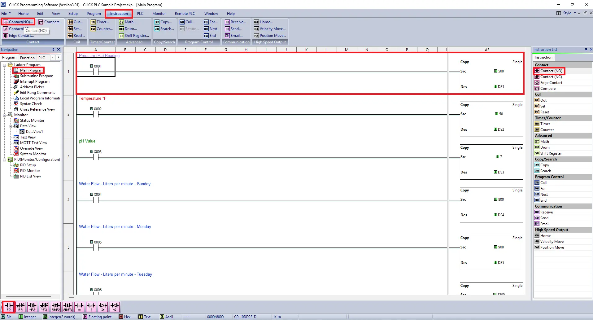
Assigning a Bit Memory Address to a Contact
– Enter the bit address : X01 (for this example)
– A green checkmark will verify the address
– Click OK to assign the address to the contact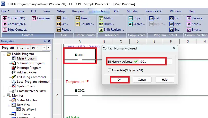
Add a Copy Function
– Select Single Copy
– Enter a value of 500 in the Source
– The Destination address will be DS1 for this example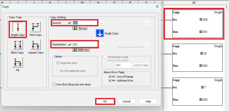
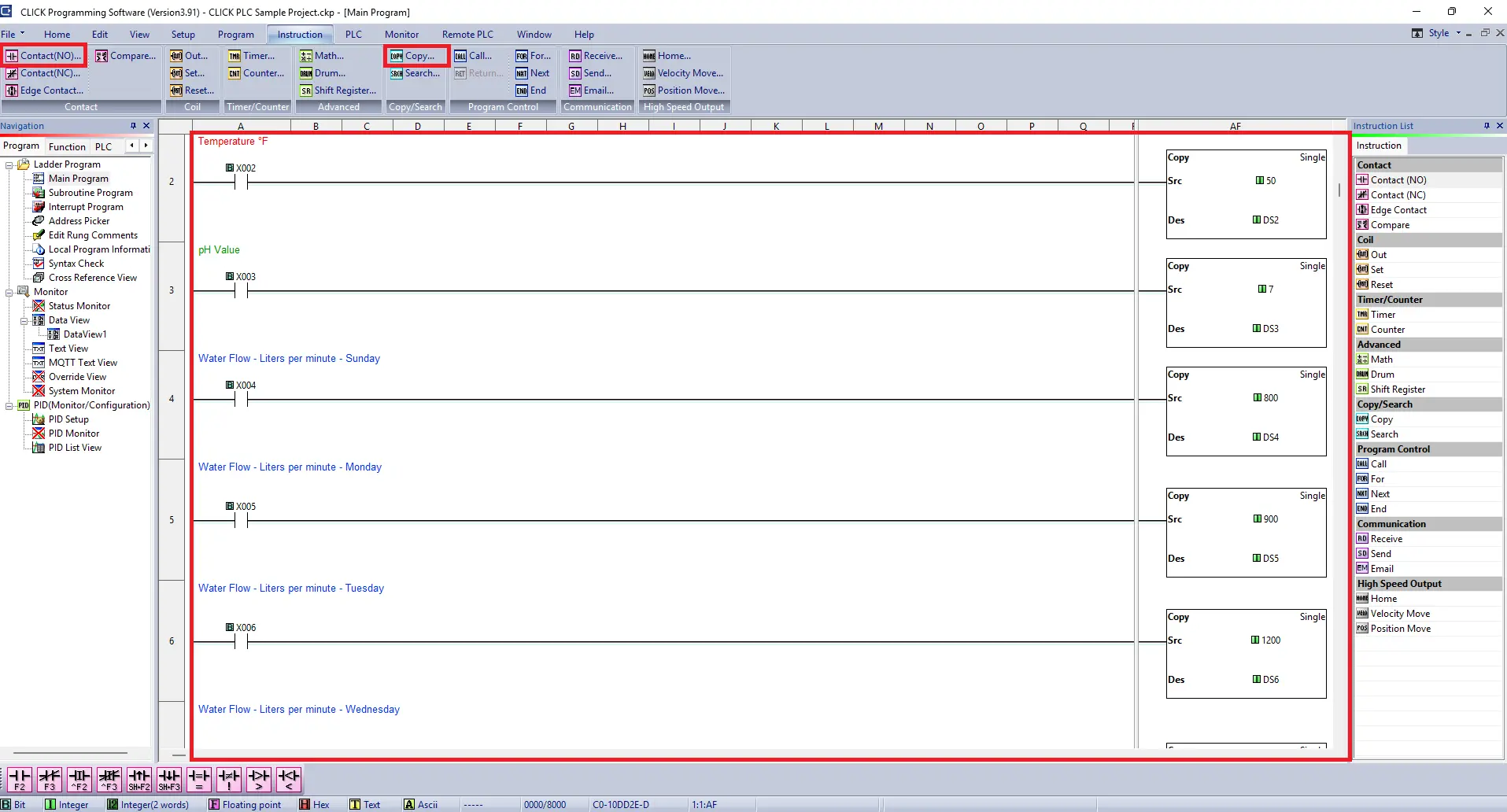
Add More Rungs
– The remaining rungs of logic in this project will be similar to first rung. Adding a normally open contact and copy function to send a value in a data register.
HMI Configuration
This section covers setting up a new EBPro project and configuring Modbus TCP/IP communication between the HMI and CLICK PLC.
EBPro Project Configuration
Follow this step-bystep guide on how to start a new project in EBPro and selecting a protocol driver.
Instructions: EBPro Project Configuration
Start a New Project
– Select the cMT3072X2 for this example
– Click OK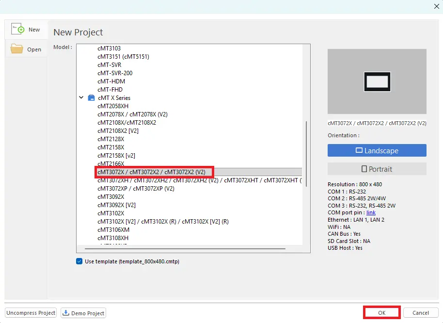
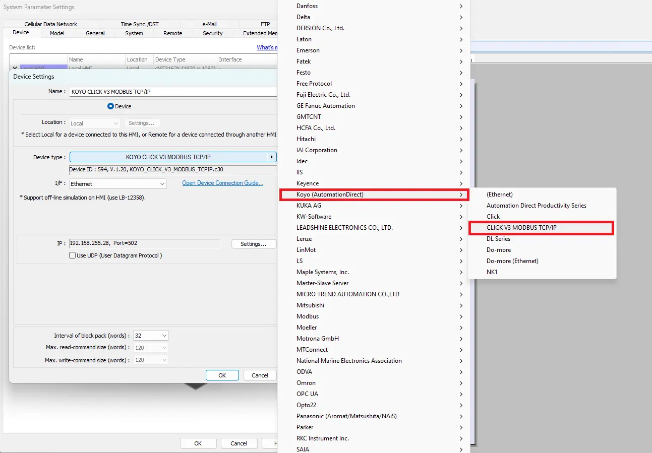
Selecting the PLC Protocol Driver
– Choose the Koyo (AutomationDirect) > CLICK V3 MODBUS TCP/IP
Enter the HMIs IP Address
– Enter the IP address of the HMI (modbus master device)
– Click OK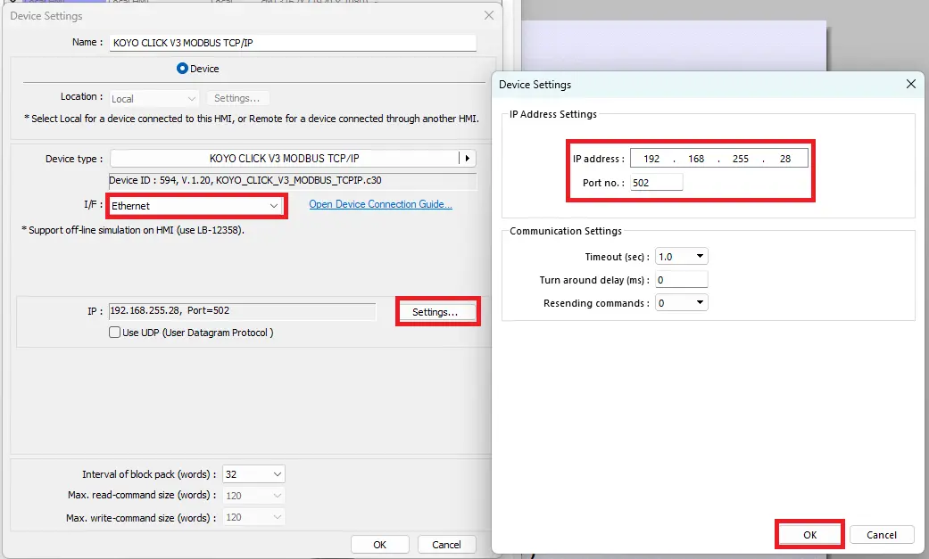
HMI Project Build
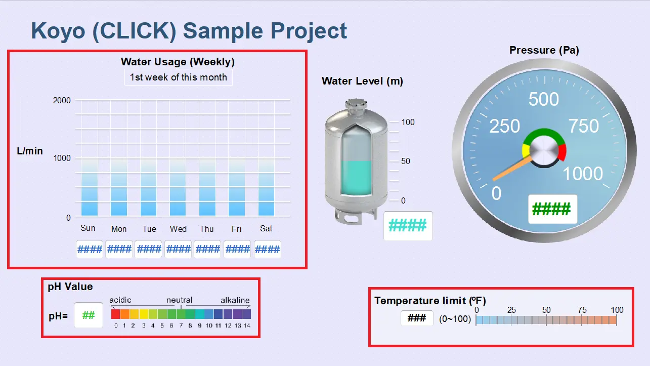
This section provides an example of how to build an HMI project by adding display objects in EBPro and linking them to PLC Modbus addresses to visualize data. This section will not cover every object, but it will help you get started.
EBPro Project Build
This step-by-step guide will get you started in adding objects in an EBPro project and assigning the CLICK PLC modbus addresses.
Instructions: EBPro Project Build
Add Object to HMI Project
– Navigate to Object on the toolbar
– Select Chart > Meter Display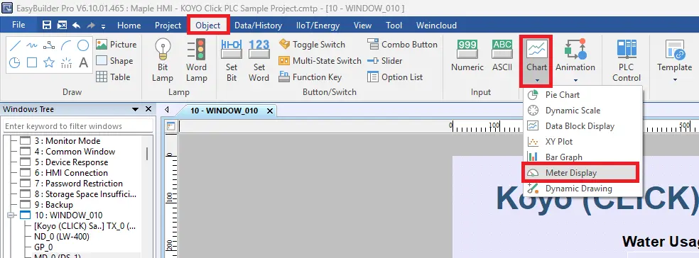
Object Properties
– Double click on the Meter Display
– Choose the KOYO CLICK V3 MODBUS TCP/IP for a device
– DS1 for the address (this is the address used in the plc logic for the pressure reading)
– Set the Value to Min:0 and Max:1000
– Range Limit: set the colors for Low, Mid, High
– Direct limits: Low limit: 200 and High limit:800
– Click Apply and OK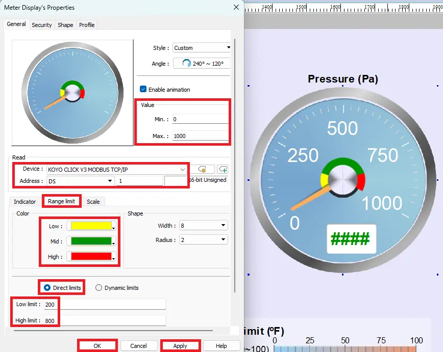
Numeric Display
– This will display the pressure reading
– Select DS1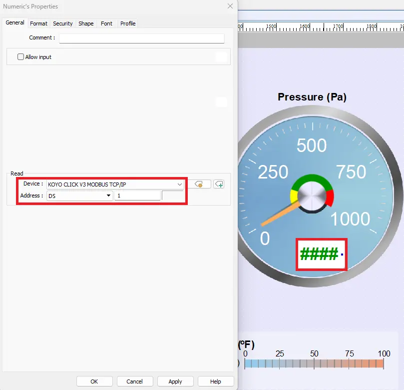
Bar Graph General Settings
– Click General
– Choose the KOYO CLICK MODBUS TCP/IP device
– Choose DS11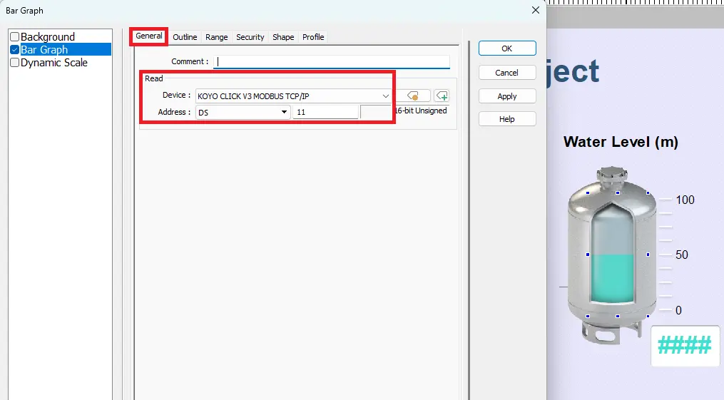
Bar Graph Outline Settings
– Click Outline
– Edit the outline of the bar graph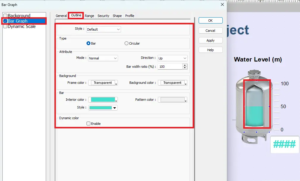
Bar Graph Range Settings
– Click Range
– Edit the Range settings of the bar graph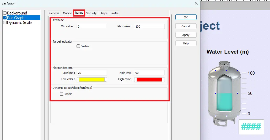
Adding Other Objects to the Project
– To learn how to add and edit the objects in this project please refer to the EBPro Programming Manual and download the sample project. Both can be found at bottom of this article
Downloading Projects
In this section, you will learn how to connect to the CLICK PLC, read and write a project, and download your HMI project using EBPro.
Downloading to PLC and HMI
Follow this step-by-step guide on how to download a project in CLICK and in EBPro.
Instructions: Downloading to PLC and HMI
Connect to PLC
– Navigate to the PLC tab
– Select Connect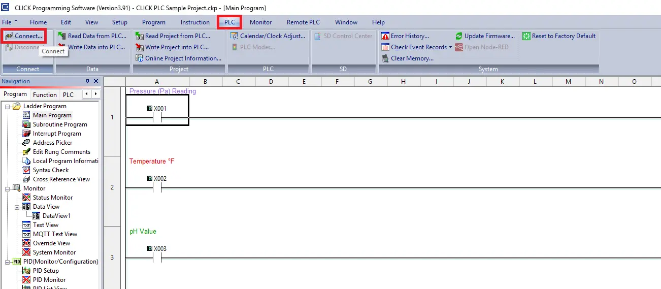
USB Connection
– Port Type: USB
– COM Port No: COM3 (for example)
– Click Connect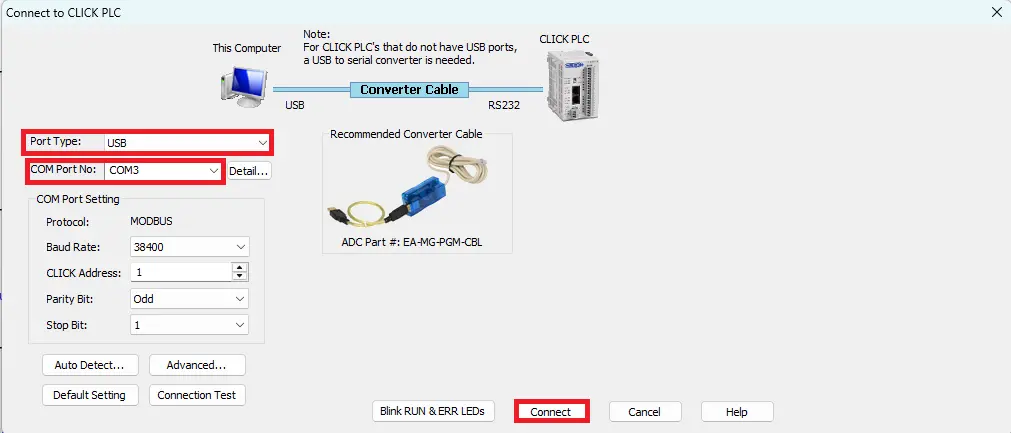
Reading Project from PLC
– Choose Read the project from the PLC (in this example)
– Click OK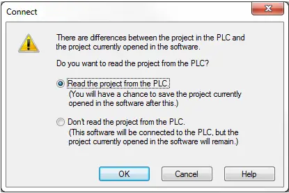
Login
– Enter the User Name and Password that was chosen when you created the PLC project.
– Click OK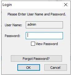
Write Project into PLC
– Navigate to the PLC tab
– Click Write Project into PLC or enter Shift+F9 on your keyboard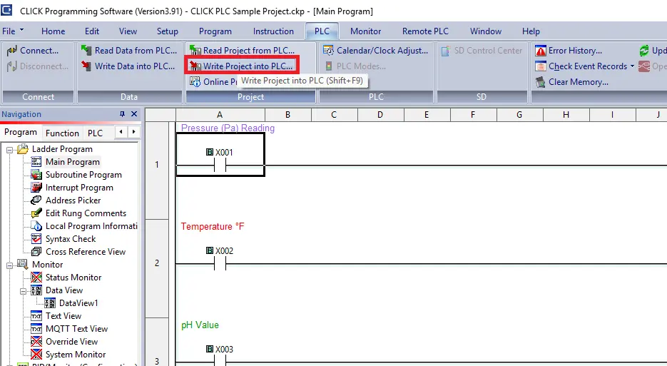
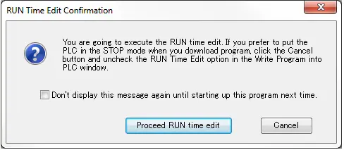
RUN Time
– Click Proceed RUN time edit
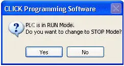
Switch to STOP Mode
– Click either Yes to switch to STOP mode or No to stay in RUN mode
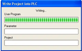
Write Project into PLC
– A window will display the writng progress
Transfer Completed
– A pop up will verify that the write is completed
– Click OK
Download to HMI in EBPro
– Navigate to the Project tab
– Click Download (PC>HMI) to open the Download window
– Enter the IP address of the HMI
– Click Download to begin the process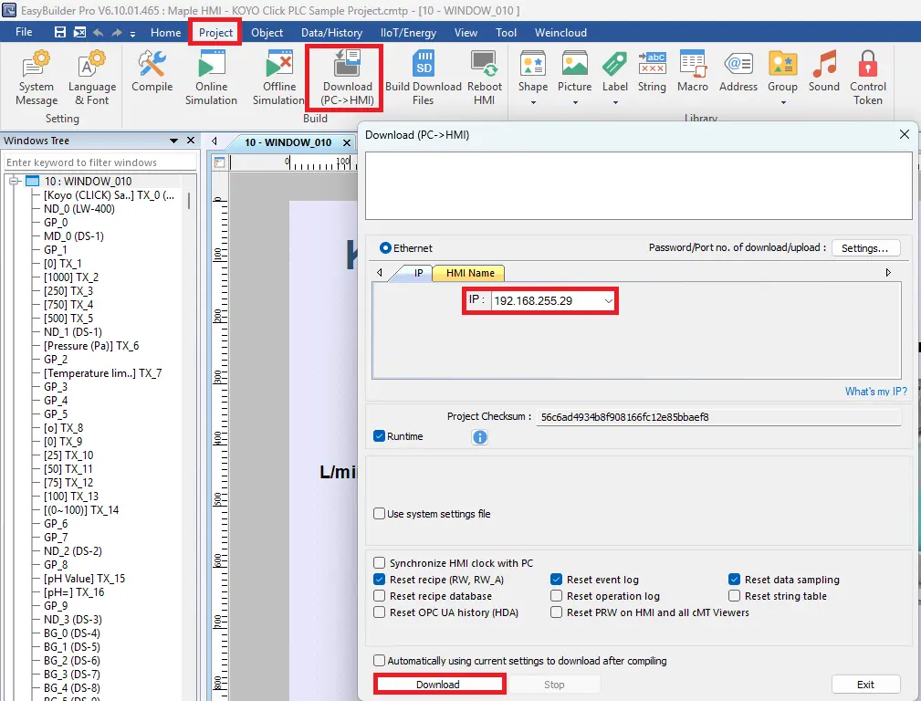
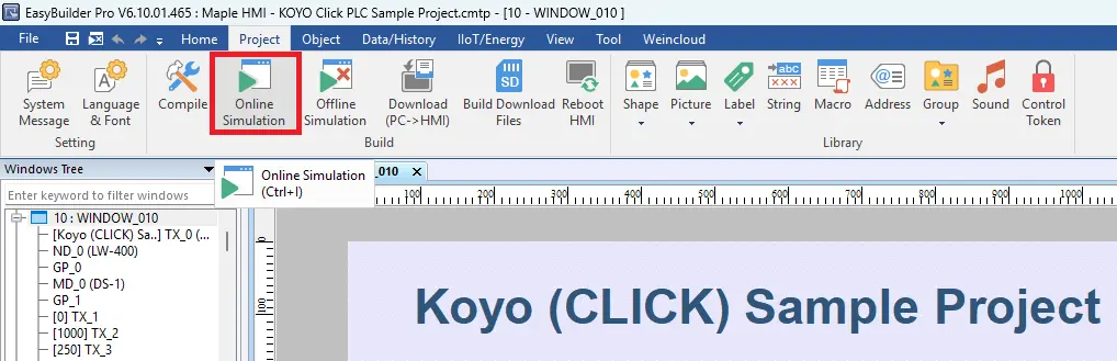
Online Simulation
– Once you have downloaded the project to the HMI, you can now view the live values. Click Online Simulation.
You are now ready to apply your Maple Systems HMI and CLICK PLC in real-world applications. By combining the functionality of the CLICK PLC with the visualization and interface capabilities of the Maple Systems HMI, you are prepared to design practical automation solutions and implement them in real operating environments.
Recap
This article demonstrated how to connect a Maple Systems HMI with an AutomationDirect CLICK PLC to create a small industrial automation system. First, it walked through creating a PLC project and developing the ladder logic. Next, it explained how to configure Modbus TCP/IP communication between the PLC and the HMI. After that, it showed how to build an HMI interface in EBPro and link display objects to PLC data. Finally, the article described how to download the projects to both the PLC and the HMI and verify communication using Online Simulation.
Next Steps
As a next step, the system could be expanded to include more advanced features such as operator controls, alarms, and real input devices instead of simulated data. For example, you could connect a real pressure sensor or other field devices to the PLC. In addition, you could add start/stop buttons and mode selection on the HMI to provide operators with direct control of the process.
Furthermore, alarm notifications could be configured to alert operators when values exceed safe limits. Similarly, you could implement data logging or recipe management on the HMI. This would allow operators to track production data or adjust process parameters more easily. As a result, these additions would make the system more practical and closer to a real industrial automation application.
Sample Project
This integration tutorial uses these CLICK and EBPro sample projects.
Resources & Documentation
The following guides and documentation are specific to the hardware used in this integration tutorial and will help you with setup, configuration, and programming:
Looking for additional learning resources? Explore our library of tutorials, example projects, and software tools to help you get the most out of your system:
Also, browse our Support Center for a complete list of installation guides, FAQs, and additional technical documentation.
About the Author
Trusted source for industrial automation & control solutions
Follow Maple Systems:
Share:


