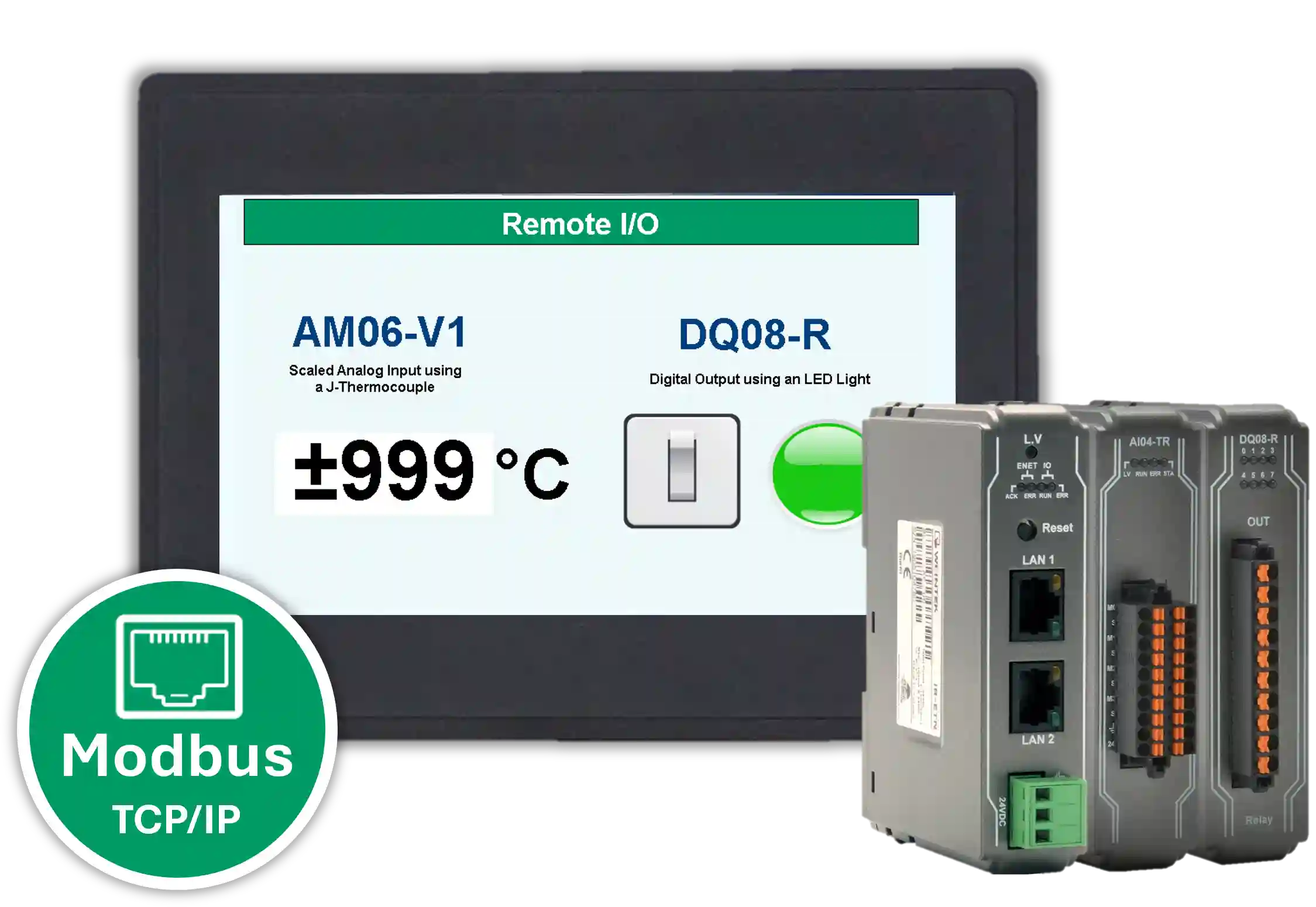
This tutorial shows you how to connect a Maple Systems HMI+PLC combo to Remote I/O over Modbus communication. In this example, the system reads analog input data from a J-type thermocouple and then controls a digital output using an LED light.
By following this guide, you will learn how to configure the required hardware, review the network and wiring layout, and use the sample project as a reference for your own application.
Software Required
Hardware Required
- HMC4070A-M — Other HMC2000 and HMC4000 models can also be used.
- iR-ETN Coupler
- AM06-VI Remote I/O
- DQ08-R Remote I/O
- 24 VDC Power Supply (4010-0011)
Network Configuration and Wiring
This wiring diagram can also be used with other compatible HMC and Remote I/O models. The J-type thermocouple and LED light are included only as examples.

For a more detailed thermocouple setup, refer to the How to Read Temperature with a J-Thermocouple using a 0-5V Analog Configuration tutorial. Additionally, for more detailed LED output setup, refer to the How to Turn an LED On and Off using Digital Output tutorial.
Ethernet Configuration
- LAN2: PC to iR-ETN Coupler
- LAN1: iR-ETN Coupler to HMC4070A-M
Power Wiring
- 24V power supply to 24V HMC4070A-M
- 24V HMC4070A-M to 24V iR-ETN Coupler
- 0V power supply to 0V HMC4070A-M
- 0V HMC4070A-M to 0V iR-ETN Coupler
Analog Input – J Thermocouple Wiring
- Thermocouple to CH1 V1+ on AM06-VI
- Thermocouple to CH1 V1- on AM06-VI
Digital Output – LED Light Wiring
- DQ08-R CH0 to LED light
- DQ08-R C0 to LED light
User Interface

Final Thoughts
Connecting an HMI+PLC combo to Remote I/O over Modbus is a practical way to expand your automation system. With this setup, you can read analog input data from field devices and control digital outputs from the same application.
Additionally, by using the sample hardware, wiring layout, and project files in this tutorial, you can build a working reference project and adapt it to your own application requirements. For more information, please reach out to Maple Systems technical support.
Sample Project
The sample project shown above was designed for the specific hardware listed at the beginning of this tutorial. Use it as a reference when programming your unit. If you are using different models, you can apply similar steps in your own project.
Resources & Documentation
The following guides and documentation are specific to the hardware used in this integration tutorial and will help you with setup, configuration, and programming:
- MAPware-7000 Getting Started Guide
- MAPware-7000 Programming Manual
- IEC 61131-3 Programming Guide for MAPware-7000
- iR-ETN User Manual
Looking for additional learning resources? Explore our library of tutorials, example projects, and software tools to help you get the most out of your system:
Also, browse our Support Center for a complete list of installation guides, FAQs, and additional technical documentation.
About the Author
Trusted source for industrial automation & control solutions
Follow Maple Systems:
Share:


