In a packaging and labeling station, a camera mounts above the conveyor and connects to the Maple Systems HMI to monitor labeling. When sensors detect a jam, missing product, or label fault, the HMI automatically switches to the corresponding live camera view. Operators immediately see the condition that triggered the fault, such as a skewed label, stopped carton, or mechanical obstruction.
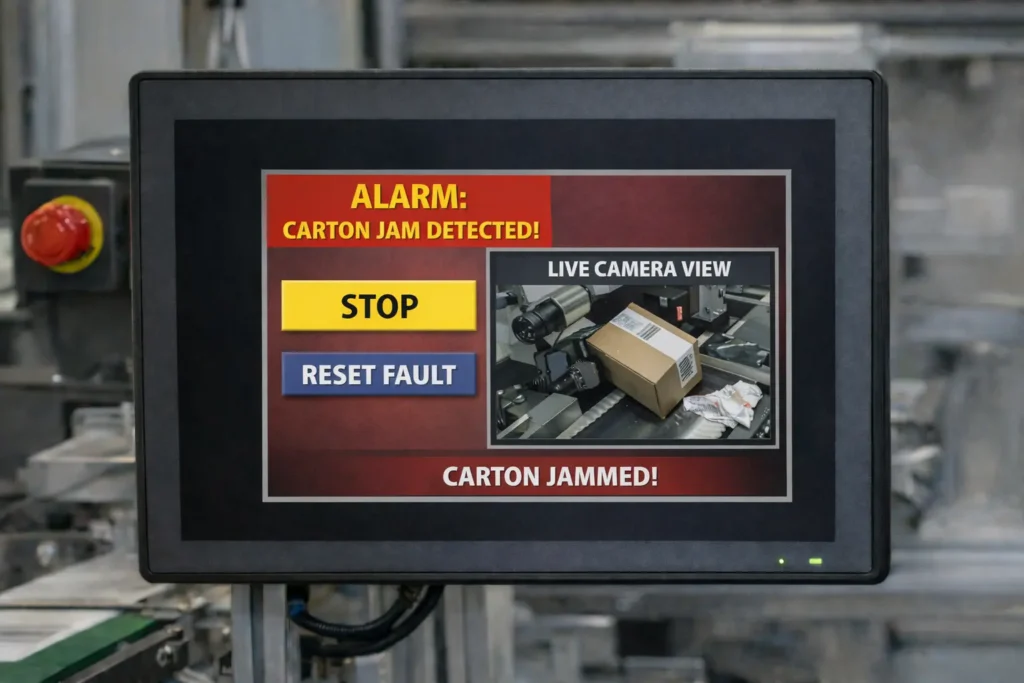
This visibility lets operators confirm issues before taking action, which reduces unnecessary stops and avoids investigating nuisance sensor faults. Viewing the exact problem location on the HMI speeds troubleshooting, allowing operators to correct issues and restart production quickly.
Such integration works well in environments where dust, debris, or product variation may cause false sensor triggers. It also helps when accessing the fault location requires time, tools, or multiple safety procedures. Connecting the camera to the HMI creates a central point for fault detection and visual verification, improving efficiency and reducing downtime.
Types of cameras commonly connected to HMIs
Industrial automation systems support several camera types, depending on inspection requirements and communication needs.
Smart vision cameras perform onboard inspections such as presence detection, position verification, barcode reading, and basic quality checks.
These devices send pass or fail results and inspection data directly to the HMI or control system.
Industrial vision systems combine a camera with a dedicated controller for higher performance inspection and measurement applications.
The controller processes images while the HMI displays results, images, and inspection status for operators.
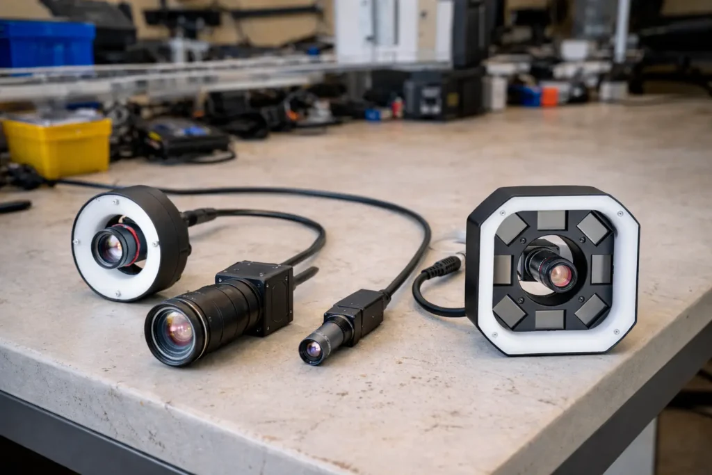
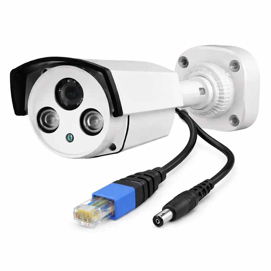
IP (Ethernet) cameras provide live monitoring by streaming video to the HMI over the plant network. They support setup verification, jam monitoring, and operator visibility across multiple stations. Many models include Power over Ethernet, allowing one cable to supply power and communication while reducing installation complexity.
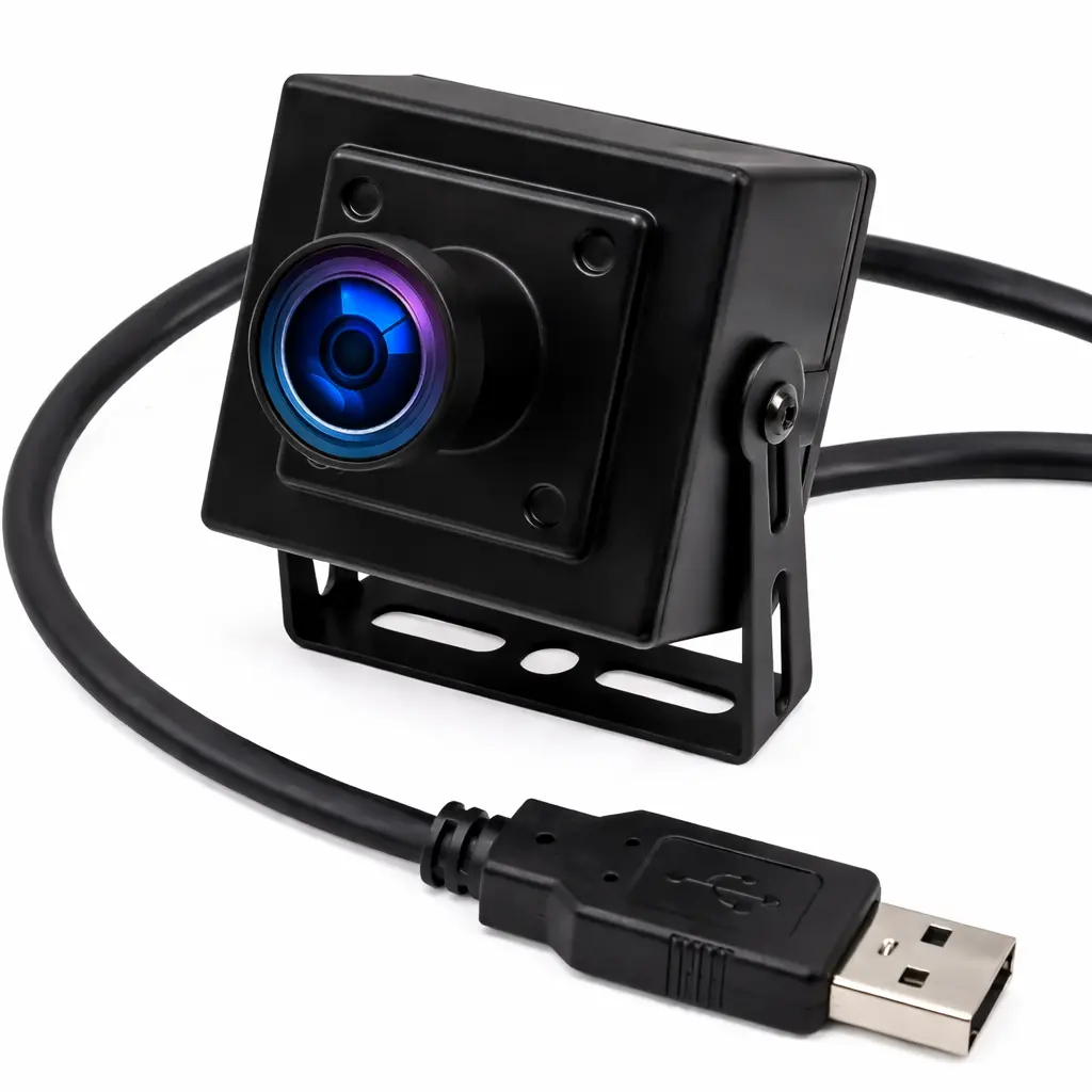
USB cameras connect directly to the HMI and support simple local viewing applications without requiring network infrastructure.
Software Required
Hardware Required
- Any Maple Systems HMI can be used. (cMT2108X2v2 used in this example)
- Camera (an IP Camera and USB camera are used in this example)
Network Diagram and Camera Configuration

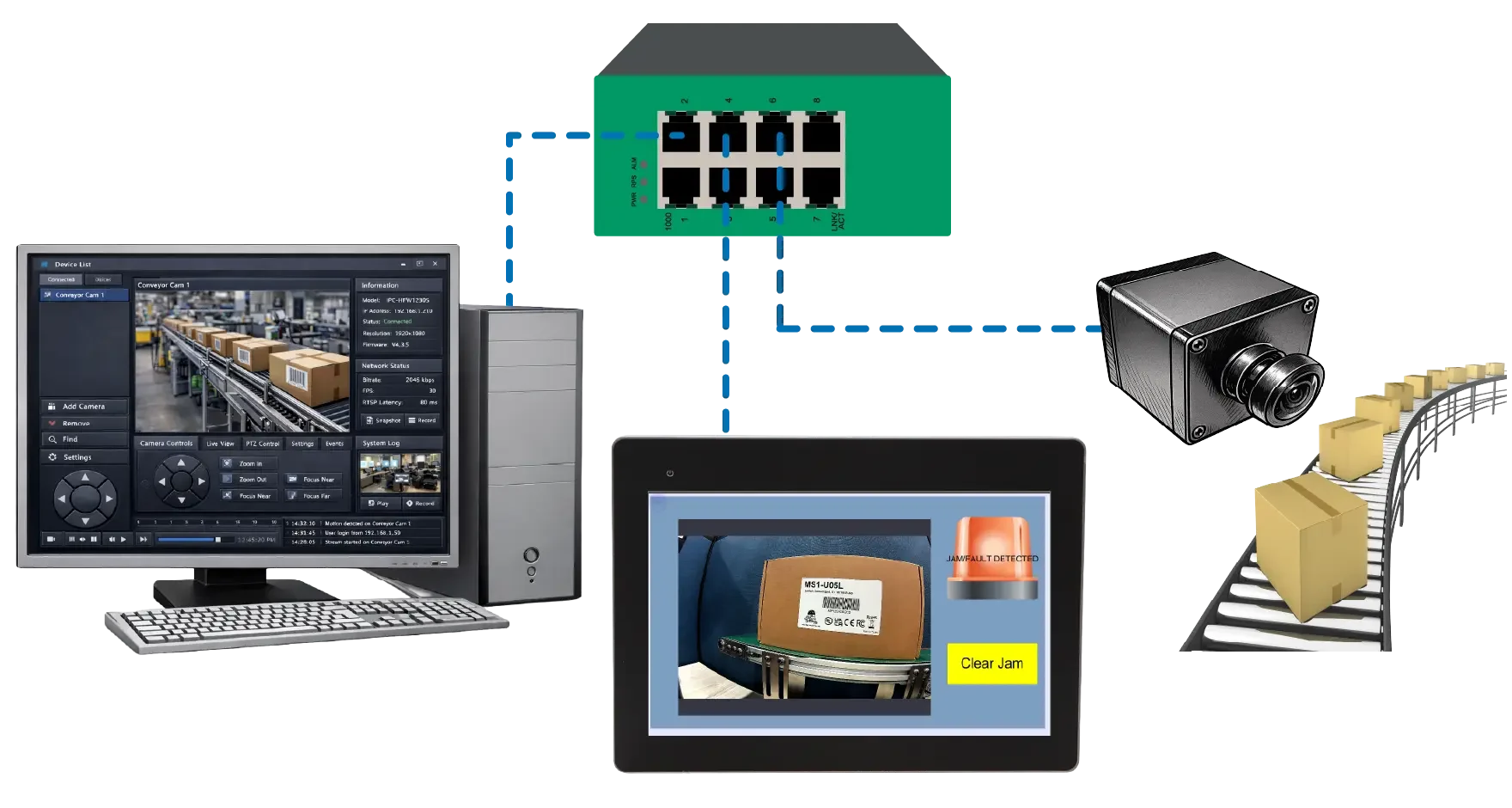
In the diagram, a PC running IP camera software with IP address 192.168.255.58 connects to the network switch. The PC interface shows a live camera view and control software, allowing users to monitor or configure the camera directly.
A 10 inch HMI with IP address 192.168.255.114 also connects to the switch. The HMI screen displays an “IP Camera Sample Project,” showing that the HMI receives and displays the camera video stream over the network.
An IP camera with IP address 192.168.255.116 sits near a conveyor with boxes to represent a typical industrial inspection or monitoring application. The camera streams video through the network switch to both the HMI and the PC at the same time.
All devices share the same subnet.

In the USB camera diagram, a PC with IP address 192.168.255.58 connects to the switch so it can communicate with the HMI for programming, monitoring, or data access over the network. The PC only needs to upload or download the project during setup.
A 10 inch HMI with IP address 192.168.255.114 also connects to the switch. The HMI screen displays a “USB Camera Sample Project,” showing that the operator interface can view live video. Unlike the IP camera example, the camera does not connect through the network.
A USB camera sits near a conveyor carrying boxes to represent a typical machine monitoring or inspection application. A direct cable connects the camera to the HMI, sending the video signal through USB instead of Ethernet.
The PC and HMI share the same subnet. The PC is only used to initially download the project to the HMI.
Camera Configuration on an HMI
Now you’ll need to configure the camera within the EBPro programming software so the HMI can communicate with and display the video feed correctly.
Setup Camera in EBPro
Read the following steps to configure a camera in EBPro
Instructions: Setup Camera in EBPro
Add Video In Object
– Navigate to the object tab
– Select Media
– Select Video In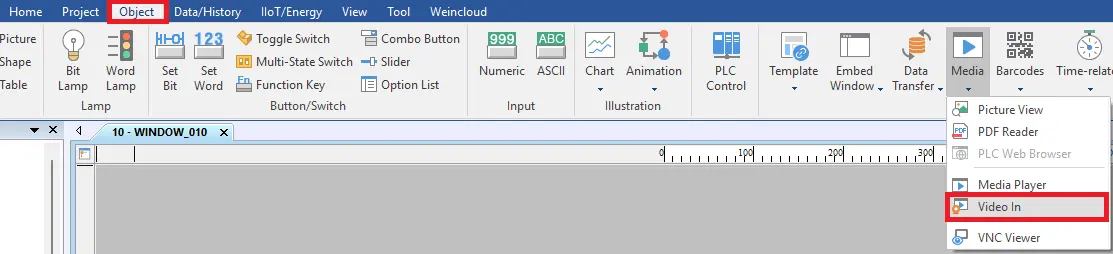
Select IP Camera
– Select IP Camera
– Type the RTSP url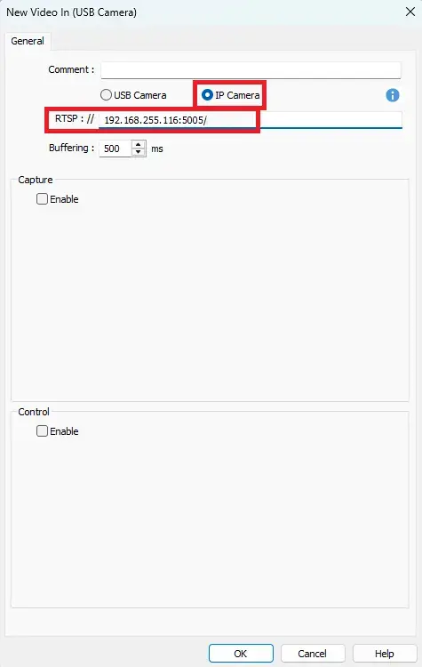
Capture and Control
– Select Enable
– Under Control select enable to use pause control and dynamic RTSP URL.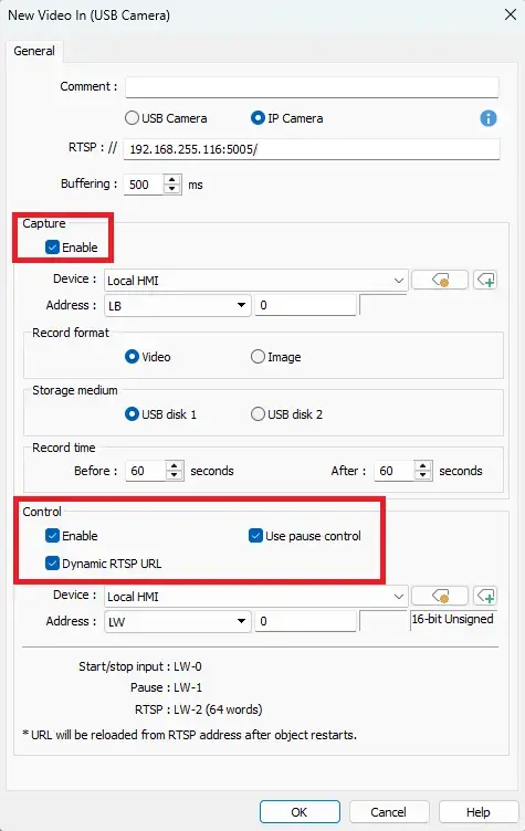
Select USB Camera
– Select USB Camera
– Under Capture select Enable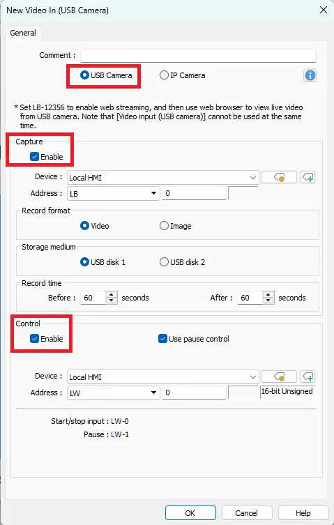
HMI Project Build
Now you’ll need to build the project in the EBPro programming software. This involves adding the camera object to your project, entering the appropriate connection settings, and verifying that the live camera image appears on the screen. Once configured, you can download the project to the HMI and confirm proper operation during runtime.
Building a Camera Project in EBPro
In the following steps, you will learn how to simulate a conveyor jam fault using internal HMI bits and trigger a camera popup when the fault/jam occurs. A USB camera will be used in this example.
Instructions: Building a Camera Project in EBPro
Add a Set Bit
– Add a Set Bit to the main window in the project
– After adding the Set Bit, open the properties
– Assign LB-100 as the write address
– Attribute syle as Set ON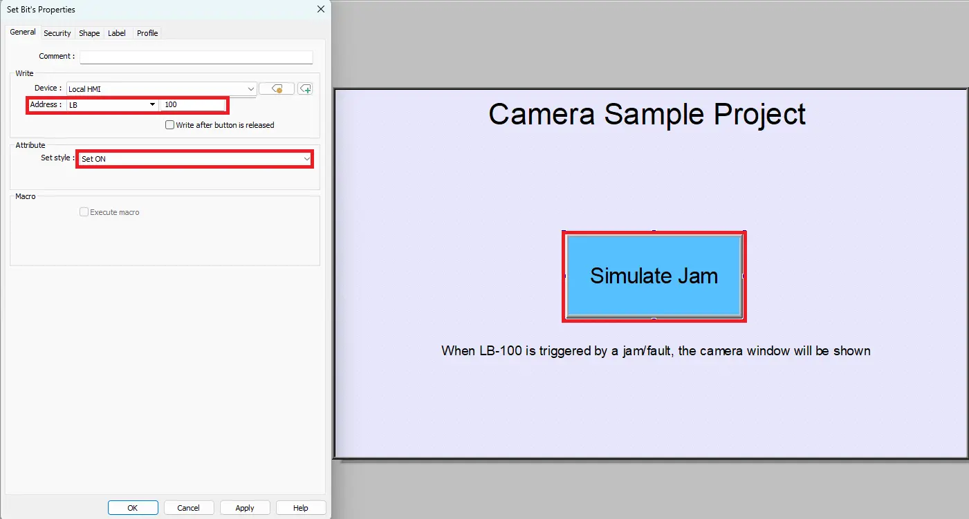
Create another window
– Create another window for the jam/fault detection camera feed
– Name it Jam/Fault Detection Camera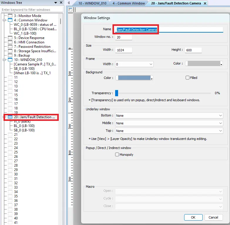
Add Video In (USB Camera) object
– Place the object in the project (Jam/Fault Detection Camera window)
– Select USB Camera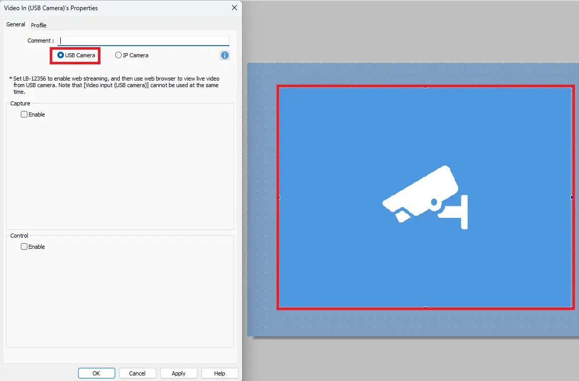
Add Bit Lamp object
– Place the Bit Lamp in the project (Jam/Fault Detection Camera window)
– Assign LB-100 as the Read Address
– Change the Bit Lamp image to one of your choosing
– This is optional. Change the Blinking state to Blinking on state 1 and Breaking time to 0.5 second(s)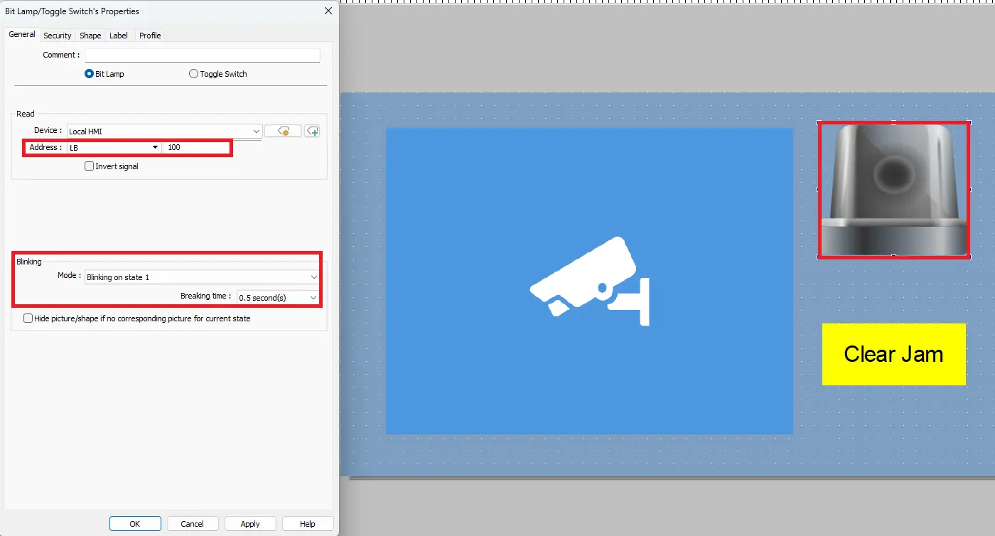
Add Set Bit
– Place the Set Bit in the project (Jam/Fault Detection Camera window)
– Assign the write address to LB-100
– Attribute to Momentary. This can also just be assigned to Set OFF.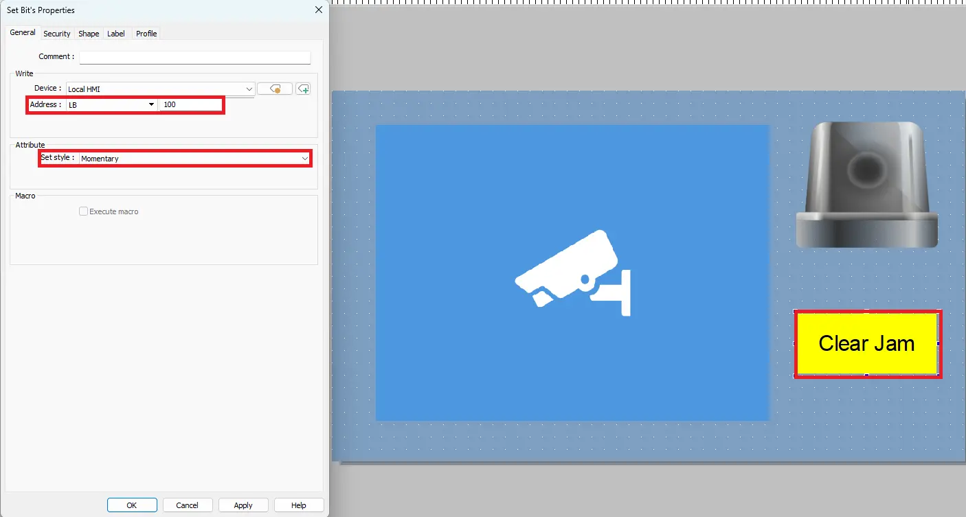
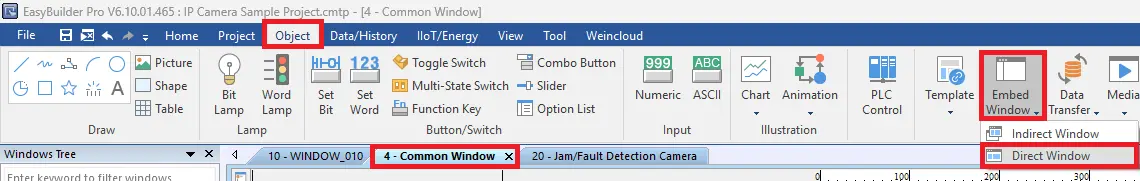
Add a Direct Window to the Common Window
– Go to Object > Embed Window > Direct Window
Direct Window Properties
– Place the Direct Window anywhere in the Common Window and expand it to the fill the entire window
– Open the Direct Window Properties
– Window/No: Jam/Fault Detection Camera
– Attribute set to Trigger: ON
– Style set to Popup Window
– Assign LB-100 to the read address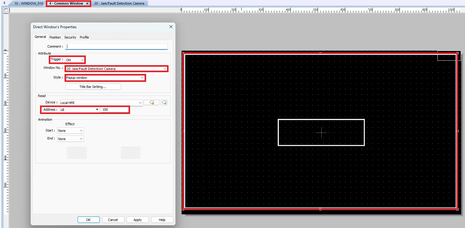
Download Project to HMI
– Go to Download on the toolbar
– Enter the IP Address and press Download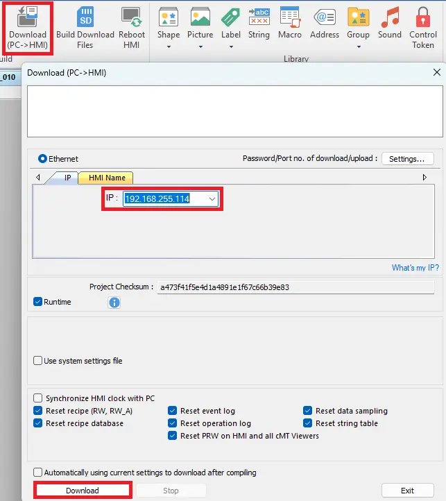
Live Simulation
Now simulate the jam/fault scenario using the sample project that was just created in EBPro. Download the project to the HMI and try it out.
When the simulated jam condition (LB-100) is triggered, the system is designed to open a camera window automatically to display the live feed associated with the jam/fault. The demonstration illustrates how an HMI can use an internal fault bit to trigger visual diagnostics, allowing operators to view the problem area and then clear the fault once the condition is resolved.
Recap
This article explained how cameras can be integrated with a Maple Systems HMI to provide real-time visualization and support troubleshooting in industrial automation applications such as packaging and labeling stations. It covered the differences between IP cameras, USB cameras, smart vision cameras, and controller-based vision systems. You also learned how to configure and display camera feeds in EBPro, including setting up RTSP connections, enabling controls, building the HMI project, and downloading it to the device. Live simulation examples demonstrated how camera integration improves operator visibility, fault verification, and overall equipment efficiency.
Next Steps
To continue building your application, you can expand the project by integrating camera data with PLC logic, alarms, or production tracking functions. Consider adding automated triggers to display the camera feed during faults, logging images for quality records, or linking barcode or vision results to machine decisions such as sorting or reject mechanisms. You may also explore advanced features such as remote HMI access, multiple camera views, or integration with smart vision systems for automated inspection.
Sample Projects
This integration tutorial uses the EBPro Sample Project.
Resources & Documentation
The following guides and documentation are specific to the hardware used in this integration tutorial and will help you with setup, configuration, and programming:
Looking for additional learning resources? Explore our library of tutorials, example projects, and software tools to help you get the most out of your system:
Also, browse our Support Center for a complete list of installation guides, FAQs, and additional technical documentation.
About the Author
Trusted source for industrial automation & control solutions
Follow Maple Systems:
Share:


