
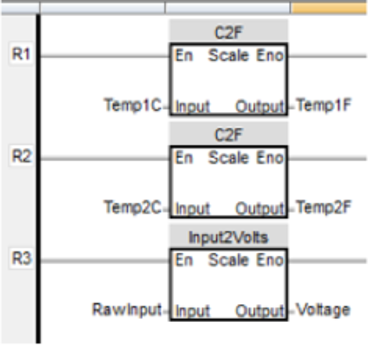
The Ladder Diagram editor uses the same programming paradigm as the Native Ladder editor. It is a graphic editor in which instructions are placed in a pseudo electromechanical circuit. Instructions are activated by connecting them to the power rail of the circuit. Boolean operators are modeled as relay contacts and coils.
Contacts can be arranged to block or allow power to flow from the power rail to downstream instructions based on the needs of the application. Coil instructions are activated when the circuit is on a logical state that allows power to flow to them.
Software Downloads & Upgrades
Manuals & Guides
- HMC Series Installation Guide
- MAPware-7000 Programming Manual
- Mapware-7000 Getting Started Guide
- HMC3000 I/O Module Guide
- HMC7000 I/O Module Guide
- MAPware-7000 IEC61131 Programming Guide
- MLC Series PLC Programming Manual & Installation Guide
- MLC I/O Module Guide
Videos
- Product Overview
- Part 1: Introduction and Installation
- Part 2: Creating a Native Ladder Project
- Part 3: Adding and Initializing Tags
- Part 4: Adding Logic
- Part 5: Creating an HMI Screen
- Part 6: Duplicationg an HMI Screen
- Part 7: Downloading and Testing the Project
- Part 8: Creating an IEC Project
- Part 9: Creating a UDFB
- Part 10: Adding a Structure Text UDFB
- Part 11: Adding Power Up and Main Routine Logic
- Part 12: Creating Screen Objects
- Part 13: Downloading the Project and Online Monitoring
Sample Projects