In this tutorial, you’ll learn what a VLAN is and why it’s useful. We’ll also show you how to manage your VLAN using a Maple Systems Lite-Managed Industrial Network Switch with the MapleLink Lite user interface.
*Important note* You can ONLY manage a VLAN with a Lite-Managed Network Switch. In order to fully configure VLANS you need a fully managed network switch MS1-M08G. Please refer to the Industrial Network Switch Operations Manual – Managed Series 5.3 VLAN
A VLAN (Virtual Local Area Network) is a technology used in networking to create logically separate networks within the same physical network infrastructure.
Here’s a simple breakdown:
- A traditional LAN connects devices in a physical area (like all computers on one floor of a building).
- A VLAN lets you split that physical network into multiple virtual networks, even if the devices are in different locations.
- Devices on the same VLAN can communicate with each other directly, as if they were on the same physical network.
- Devices on different VLANs cannot communicate without a router or Layer 3 switch.
Software Required
- MapleLink Lite User Interface (Enter the network switch’s IP address into a web browser to access its web interface.)
Hardware Required
- MS1-L05G01F
- MS1-L08G
- Embedded Industrial Box PC (A web browser is required. Use one of our Industrial Box PCs.)
Why use VLANs?
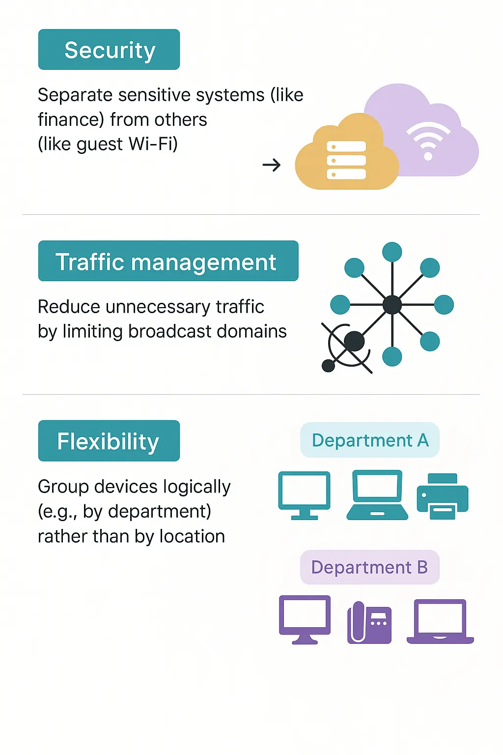
Example:
In an office building:
- VLAN 10 = HR department
- VLAN 20 = IT department
- VLAN 30 = Guest Wi-Fi
Even if all are plugged into the same switch, they can’t see or talk to each other unless you set up routing between them.
Port Isolation
Port-based VLANs (also called port isolation) let you separate switch ports into their own private groups. Each port’s traffic stays within its own group and cannot be sent to ports outside that group. This works independently of VLAN tags—it ignores any VLAN IDs in the packets.
Port isolation is set up individually for each port by specifying its egress ports (the ports it’s allowed to send traffic to).
- If the CPU port (port 0, the switch’s management interface) is not set as an egress port, devices on that port will not be able to manage the switch.
- To let two isolated ports communicate, you must add each one to the other’s egress port list.
- By default, the CPU port is part of a VLAN with all Ethernet ports. If a port is removed from this VLAN, you cannot manage the switch from that port.
Configuration
| Node | Command | Description |
| enable | show port-isolation | This command displays the current port isolation configurations. “V” indicates the port’s packets can be sent to that port. “-” indicates the port’s packets cannot be sent to that port. |
| interface | port-isolation ports PORTLISTS | This command configures a port or a range of ports to egress traffic from the specific port. |
| interface | no port-isolation | This command configures all ports to egress traffic from the specific port. |
Example: If you want to allow port-1 and port-3 to talk to each other, you must configure as below:
- L2SWITCH(config)#interface 1/0/1
- L2SWITCH(config-if)#port-isolation ports 3
- L2SWITCH(config-if)#exit
Allow the port-1 to send its ingress packets to port-3.
- L2SWITCH(config)#interface 1/0/3
- L2SWITCH(config-if)#port-isolation ports 1
- L2SWITCH(config-if)#exit
Allow the port-3 to send its ingress packets to port-1
Web Configuration Port Isolation
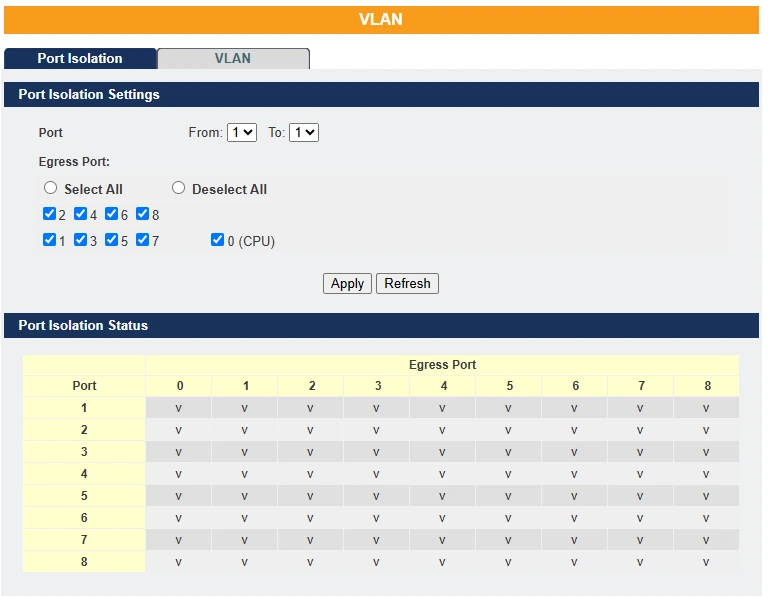
| Parameter | Description |
| Port | Select a port number to configure its port isolation settings. Select All Ports to configure the port isolation settings for all ports on the Switch. |
| Egress Port | An egress port is an outgoing port, that is, a port through which a data packet leaves. Selecting a port as an outgoing port means it will communicate with the port currently being configured. |
| Select All/ Deselect All | Click Select All to mark all ports as egress ports and permit traffic. Click Deselect All to unmark all ports and isolate them. Deselecting all ports means the port being configured cannot communicate with any other port. |
| Apply | Click Apply to configure the settings. |
| Refresh | Click this to reset the fields to the last setting. |
| Port Isolation Status | “V” indicates the port’s packets can be sent to that port. “-” indicates the port’s packets cannot be sent to that port. |
VLAN ID
A VLAN ID (VID) is a number that identifies a Virtual LAN, based on the IEEE 802.1Q standard. It’s a 12-bit value, so there can be up to 4,096 possible IDs.
- VID 0 is reserved for priority-tagged frames.
- VID 4095 is reserved by the standard.
That leaves 4,094 usable VLAN IDs.
In a tagged VLAN, the VLAN ID is added to the Ethernet frame header so switches and bridges know which VLAN the frame belongs to. This lets VLANs span multiple switches.
VLANs can be set up manually (static) or automatically (dynamic) using protocols like GVRP.
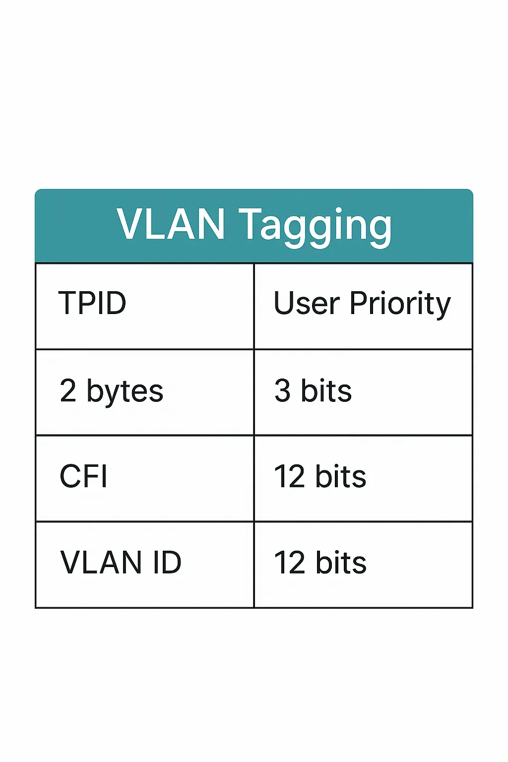
A tagged Ethernet frame is 4 bytes longer than an untagged frame. The extra 4 bytes include:
- TPID (Tag Protocol Identifier) – 2 bytes, stored in the type/length field.
- TCI (Tag Control Information) – 2 bytes, containing the priority, CFI, and VLAN ID.
Inside the TCI:
- CFI (Canonical Format Indicator) – 1 bit. For Ethernet, it’s always 0. If it’s 1, the frame can’t be sent to untagged ports.
- The next 12 bits hold the VLAN ID.
Note: VLAN ID and priority are separate. A priority-tagged frame has VID = 0, meaning it only carries priority info, and the port’s default VLAN is assumed.
Forwarding Tagged and Untagged Frames
Each switch port can process both tagged and untagged Ethernet frames.
- To a VLAN-unaware switch: The switch removes the VLAN tag before sending the frame.
- From a VLAN-unaware switch: The switch adds a VLAN tag using the port’s default VLAN ID (PVID)—usually VLAN 1, but it can be changed.
For broadcast and multicast traffic, frames are only sent to ports in the same VLAN (same VLAN ID) and never back out the port they came in on. This keeps traffic contained within its VLAN.
802.1Q Port-Based VLANs
In port-based VLANs, each switch port is permanently assigned to one VLAN. Any device plugged into that port becomes part of that VLAN and can only talk to devices in the same VLAN—communication with other VLANs requires a Layer 3 device (like a router).
The devices themselves don’t need to know about VLANs; they just work in their subnet. The switch handles VLAN tagging and makes sure traffic stays within the VLAN, blocking any leaks between VLANs.
This method is straightforward, fast, and easy to manage—especially when done in hardware using ASICs, which handle port-to-VLAN mapping at full speed without using the CPU.
Port Isolation
Port isolation is a port-based VLAN feature that divides switch ports into virtual private domains on a per-port basis. Ports in different isolation domains cannot communicate, regardless of VLAN tag information. Each port must be explicitly configured with its allowed egress ports—the ports it’s allowed to forward traffic to.
If the CPU port (port 0) is not included as an egress port for a given port, then devices connected to that port cannot access the switch for management. By default, the CPU port belongs to a VLAN that includes all Ethernet ports, allowing for management access. To allow communication between two isolated subscriber ports, each must list the other as an egress port.
Notice:
Maximum allowable VLAN’s to configure on the device are 5.
Access port:
- Connects to a single device (like a PC).
- Carries traffic for only one VLAN (untagged).
- Each access port has a PVID (default VLAN ID), which is usually VLAN 1.
Trunk port:
- Connects to another switch.
- Can carry traffic for up to 5 VLANs at the same time.
- Traffic is tagged with its VLAN ID, but the default PVID is VLAN 1.
Default Settings
All ports join in the VLAN 1.
CLI Configuration
| Node | Command | Description | |
| enable | show vlan VLANID | This command displays the VLAN configurations. | |
| configure | vlan <1~4094> | This command enables a VLAN and enters the VLAN node. | |
| configure | no vlan <1~4094> | This command deletes a VLAN. | |
| vlan | show | This command displays the current VLAN configurations. | |
| vlan | name STRING | This command assigns a name for the specific VLAN. The VLAN name should be the combination of the digit or the alphabet or hyphens (-) or underscores (_). The maximum length of the name is 16 characters. | |
| vlan | no name | This command configures the vlan name to default. Note: The default vlan name is “VLAN”+vlan_ID, VLAN1, VLAN2,… | |
| vlan | fixed PORTLISTS | This command assigns ports for permanent member of the vlan. | |
| vlan | no fixed PORTLISTS | This command removes all fixed member from the vlan. | |
| vlan | tagged PORTLISTS | This command assigns ports for tagged member of the VLAN group. The ports should be one/some of the permanent members of the vlan. | |
| vlan | no tagged PORTLISTS | This command removes all tagged member from the vlan. | |
| vlan | untagged PORTLISTS | This command assigns ports for untagged member of the VLAN group. The ports should be one/some of the permanent members of the vlan. | |
| vlan | no untagged PORTLISTS | This command removes all untagged member from the vlan. | |
| interface | acceptable frame type (all|tagged|untagged) | This command configures the acceptable frame type. all – acceptable all frame types. tagged – acceptable tagged frame only. untagged – acceptable untagged frame only. | |
| interface | pvid VLANID | This command configures a VLAN ID for the port default VLAN ID. | |
| interface | no pvid | This command configures 1 for the port default VLAN ID. | |
| config | interface range gigabitethernet1/0/ PORTLISTS | This command enters the interface configure node. | |
| if-range | pvid VLANID | This command configures a VLAN ID for the port default VLAN ID. | |
| if-range | no pvid | This command configures 1 for the port default VLAN ID. | |
| configure | vlan range STRINGS | This command configures a range of VLAN’s and Maximum allowed VLAN’s are 5. | |
| configure | no vlan range STRINGS | This command removes a range of VLAN’s and Maximum removable VLAN’s are 5. | |
| vlan-range | 1-4 | This command will allow user to create VLAN range maximum allowed VLAN’s are 5 | |
| vlan-range | add PORTLISTS | This command adds a port or a range of ports to the vlans. | |
| vlan-range | fixed PORTLISTS | This command assigns ports for permanent member of the VLAN group. | |
| vlan-range | no fixed PORTLISTS | This command removes all fixed member from the vlans. | |
| vlan-range | tagged PORTLISTS | This command assigns ports for tagged member of the VLAN group. The ports should be one/some of the permanent members of the vlans. | |
| vlan-range | no tagged PORTLISTS | This command removes all tagged member from the vlans. | |
| vlan-range | untagged PORTLISTS | This command assigns ports for untagged member of the VLAN group. The ports should be one/some of the permanent members of the vlans. | |
| vlan-range | no untagged PORTLISTS | This command removes all untagged member from the vlans. | |
Example:
- L2SWITCH#configure terminal
- L2SWITCH(config)#vlan 2
- L2SWITCH(config-vlan)#fixed 1-5
- L2SWITCH(config-vlan)#untagged 1-3
- L2SWITCH(config)#vlan range 10-14
- L2SWITCH(config-vlan-range)# fixed 1-5
- L2SWITCH(config-vlan-range)# tagged 5
Web Configuration VLAN Settings
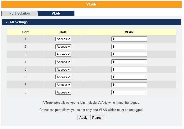
| Parameter | Description |
| Port | Select a port number to configure from the drop-down box. Select All to configure all ports at the same time. |
| Role | Select role on interface as access or trunk. |
| VLAN | User can configure maximum of 5 VLAN’s on each interface in the format 1,3,7,10,25 |
| Apply | Click Apply to save your changes back to the Switch. |
| Refresh | Click Refresh to begin configuring this screen afresh. |
Real-World Scenario
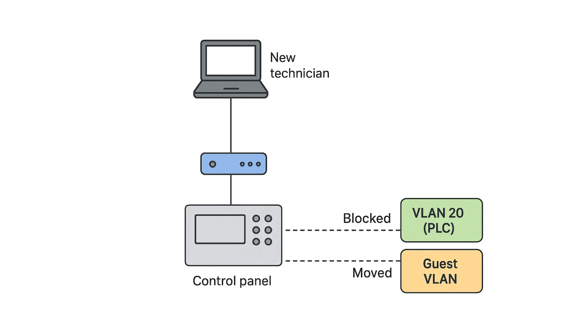
Scenario: A new technician plugs their laptop into a port near the control panel.
- If port security and VLANs are properly set:
- The port defaults to VLAN 20 (PLC) but the technician’s device gets no access because:
- Only PLC devices have static MAC entries allowed on those ports.
- Unknown MACs are either blocked or moved to a guest VLAN with no access to SCADA.
- The port defaults to VLAN 20 (PLC) but the technician’s device gets no access because:
Troubleshooting Example
Issue: SCADA workstations are unable to talk to PLCs.
Steps:
- Check that SCADA workstations are on VLAN 30.
- Verify default gateway is correct (192.168.30.1).
- Test ping to 192.168.20.1 (PLC gateway).
- Ensure inter-VLAN routing is enabled.
- Check ACLs aren’t blocking traffic between VLAN 30 and VLAN 20.
- Use “show vlan“, “show interface trunk“, and “show ip route” to inspect.
Benefits Achieved
- Isolation of broadcast traffic reduces latency in SCADA systems.
- Enhanced security posture by locking down inter-VLAN communication.
- Improved troubleshooting and scalability for network teams.
- Regulatory compliance (e.g., ISA/IEC 62443 industrial cybersecurity standards).
Summary
Virtual LANs in an industrial automation setting provide structured isolation and clear traffic flows for:
- Critical OT systems (PLCs, SCADA)
- Office IT systems
- Security and voice
- Guest and unmanaged devices
This design enhances security, stability, and performance, and allows future growth as the factory adds new production lines or upgrades control systems.
Resources & Documentation
Lite-Managed Network Switches Resources:
- Industrial Network Switches
- Industrial Lite-Managed Network Switches – MS1 Series Datasheet
- MS1-L05G01F Quick Start Guide
- MS1-L08G Quick Start Guide
- What is a network switch?
- Industrial Network Switch Operations Manual – Lite-Managed Series
More
Tutorials
Sample Projects
Software Downloads
See our Support Center for a complete list of Quick Start and Installation Guides
About the Author
Trusted source for industrial automation & control solutions
Follow Maple Systems:
