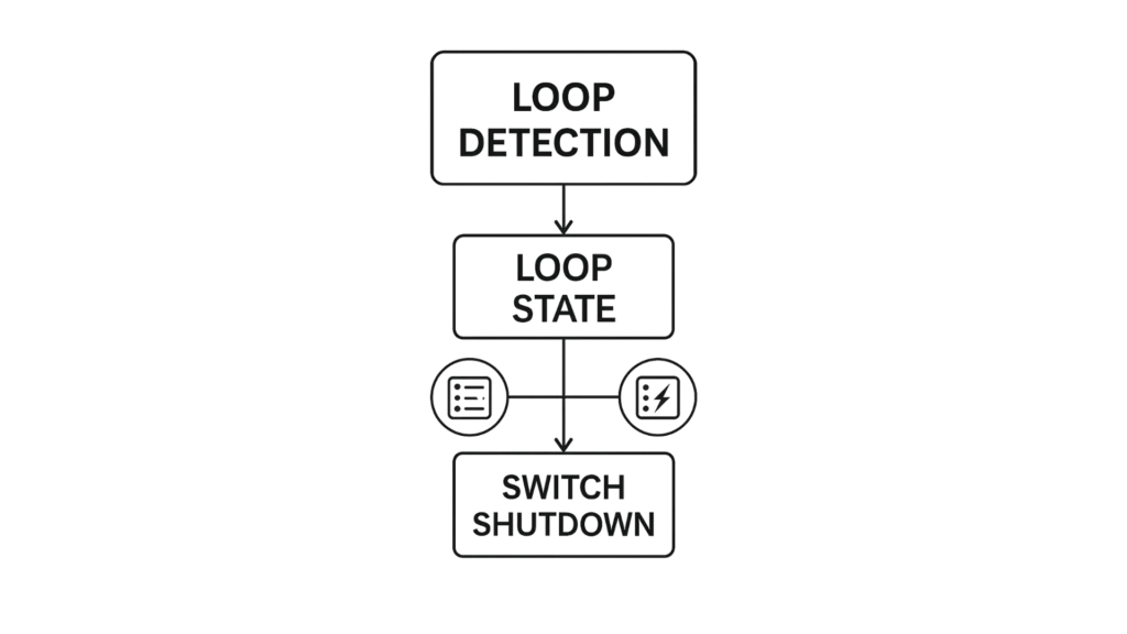
Loop Detection is designed to handle loop problems at the edge of your network. These issues can arise when a port is connected to a switch that is in a loop state. A loop state typically results from human error—specifically, when two ports on the same switch are accidentally connected by the same cable. When a switch in a loop state sends out broadcast messages, those messages continuously loop back to the switch and are repeatedly re-broadcast. This creates a broadcast storm that can severely degrade network performance.
The loop detection function sends probe packets periodically to detect if the port connect to a network in loop state. The Switch shuts down a port if the Switch detects that probe packets loop back to the same port of the Switch.

Software Required
MapleLink Lite User Interface (Enter the network switch’s IP address into a web browser to access its web interface.
Hardware Required
- MS1-L05G01F
- MS1-L08G
- Embedded Industrial Box PC (A web browser is required. Use one of our Industrial Box PCs.)
Loop Recovery
When loop detection is enabled, the switch sends a probe packet every two seconds and waits for a response. If the switch receives the same packet back on the same port it was sent from, it identifies a loop and disables that port. After a specified recovery time, the switch re-enables the port and resumes loop detection.
When the switch shuts down a port due to the loop detection feature, it generates syslog messages, internal log entries, and SNMP traps. On access switches, the Spanning Tree Protocol (STP) may not be enabled. To ensure the network topology remains loop-free in such cases, the loop detection function must also detect the following scenario:
If ports 1 and 2 form a loop and loop detection is enabled only on port 1, then port 1 will be disabled. However, if loop detection is enabled on both port 1 and port 2, both ports will be disabled.
Default Settings:
- The global Loop Detection feature is disabled by default.
- The default Loop Detection Destination MAC address is 00:0b:04:AA:AA:AB.
- Loop Detection is disabled by default on all ports.
Configuration
| Node | Command | Description |
| enable | show loop-detection | This command displays the current loop detection configurations. |
| configure | loop-detection (disable | enable) | This command disables / enables the loop detection on the switch. |
| configure | loop-detection address MACADDR | This command configures the destination MAC for the loop detection special packets. |
| configure | no loop-detection address | This command configures the destination MAC to default (00:0b:04:AA:AA:AB). |
| interface | loop-detection (disable | enable) | This command disables / enables the loop detection on the port. |
| interface | no shutdown | This command enables the port. It can unblock port blocked by loop detection. |
| interface | loop-detection recovery (disable | enable) | This command enables / disables the recovery function on the port. |
| interface | loop-detection recovery time VALUE | This command configures the recovery period time. |
| configure | interface range gigabitethernet1/0/ PORTLISTS | This command enters the interface configure node. |
| if-range | loop-detection (disable | enable) | This command disables / enables the loop detection on the ports. |
| if-range | loop-detection recovery (disable | enable) | This command enables / disables the recovery function on the port. |
| if-range | loop-detection recovery time VALUE | This command configures the recovery period time. |
Example:
- L2SWITCH(config)#loop-detection enable
- L2SWITCH(config)#interface 1/0/1
- L2SWITCH(config-if)#loop-detection enable
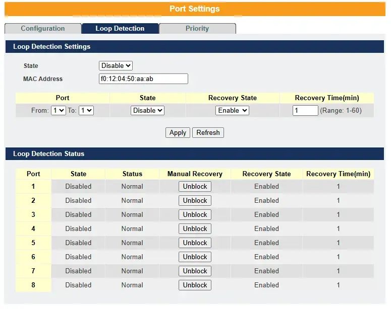
Loop Detection Web Configuration

| Parameter | Description |
| State | Select this option to enable loop guard on the Switch. |
| MAC Address | Enter the destination MAC address the probe packets will be sent to. If the port receives these same packets the port will be shut down. |
| Port | Select a port on which to configure loop guard protection. |
| State | Select Enable to use the loop guard feature on the Switch. |
| Loop Recovery | Select Enable to reactivate the port automatically after the designated recovery time has passed. |
| Recovery Time | Specify the recovery time in minutes that the Switch will wait before reactivating the port. This can be between 1 to 60 minutes. |
| Apply | Click Apply to save your changes to the Switch. |
| Refresh | Click Refresh to begin configuring this screen afresh. |
| Loop Detection Status | |
| Port | This field displays a port number. |
| State | This field displays if the loop guard feature is enabled. |
| Status | This field displays if the port is blocked. |
| Loop Recovery | This field displays if the loop recovery feature is enabled. |
| Recovery Time (min) | This field displays the recovery time for the loop recovery feature. |
Real-World Scenario
Loop Detection in Industrial Automation
Setting:
At a mid-sized manufacturing plant, the operations team is expanding a production line to accommodate a new robotic assembly station. As part of the expansion, new networking equipment and cabling are installed to support industrial controllers, HMIs (Human-Machine Interfaces), and monitoring sensors. During installation, a plant technician unknowingly attempts to “tidy up” some loose cables without notifying the network administrator.
What Happens:
In the process, the technician connects two Ethernet ports on separate control panels using a spare patch cable. Both ports happen to trace back to the same industrial-grade managed switch located in the control room. This creates an Ethernet loop—packets sent out one port are received back through the other, then loop again endlessly.
Impact:
Within minutes, network traffic between PLCs (Programmable Logic Controllers) and SCADA (Supervisory Control and Data Acquisition) systems begins to degrade. Machine status updates freeze, alarms fail to display in the control room, and the operator touchscreen panels become unresponsive. The broadcast storm triggered by the loop is overwhelming the switch and jeopardizing real-time communication critical to the automation process.
Loop Detection in Action:
Luckily, the managed switches used in the plant network have Loop Detection enabled. Upon detecting that its own probe packets are being reflected back through a different port, the switch quickly identifies the loop. It automatically disables the affected port to prevent further network disruption.
Resolution:
The control system alerts the IT/OT (Information Technology/Operational Technology) support team. A technician inspects the network cabinet and identifies the unintended patch connection. After removing the cable and verifying the setup, the port is manually reactivated. Communications between devices return to normal, and production resumes without lasting impact.
Outcome:
Because Loop Detection was proactively enabled, the plant avoided a full production halt and potential damage to automated systems. This highlights the critical importance of proper network design, change control, and built-in safeguards in industrial environments.
Resources & Documentation
Lite-Managed Network Switches Resources:
- Industrial Network Switches
- Industrial Lite-Managed Network Switches – MS1 Series Datasheet
- MS1-L05G01F Quick Start Guide
- MS1-L08G Quick Start Guide
- What is a network switch?
- Industrial Network Switch Operations Manual – Lite-Managed Series
More
Tutorials
Sample Projects
Software Downloads
See our Support Center for a complete list of Quick Start and Installation Guides
About the Author
Trusted source for industrial automation & control solutions
Follow Maple Systems:
