This tutorial shows you how to read an analog input current (4-20mA), display the raw reading, and convert the signal to more meaningful values on the User Interface.
Software Required
Hardware Required
- HMC4070A-M – Other HMC2000/HMC4000 models can also be used
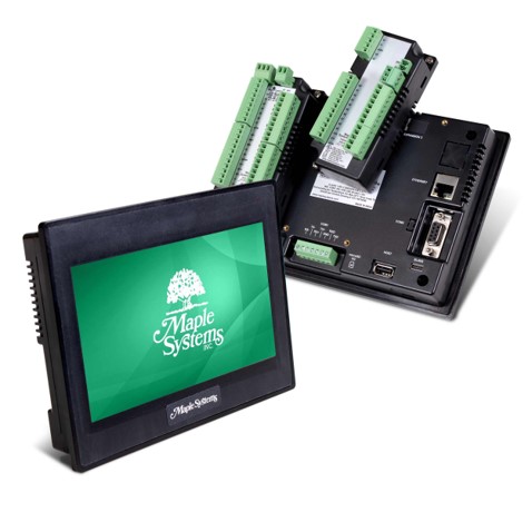
HMI + PLC Combo
Software Code (Pump Overload Scenario)
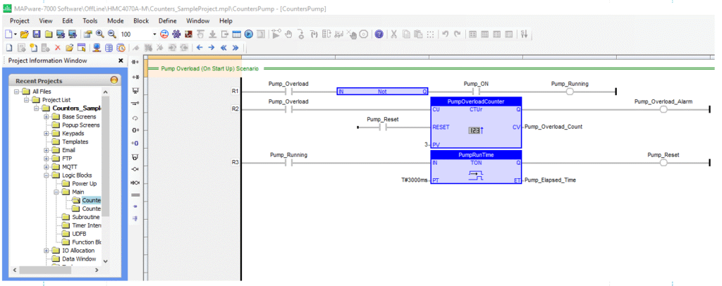
Ladder Diagram
Rung 2: Turn the “PumpOverload” bit ON 3 successive times. While running through an UP Counter with Rising Edge Detection, it will trigger the “Pump_Overload_Alarm”. Then acknowledge the alarm.
Rung 1: When the “Pump_Overload” bit is turned ON in Rung 2 it will also turn it on in Rung 1. This logic is here to prevent the “Pump_Running” bit from turning ON while the “Pump_Overload” bit is ON. The “Pump_Running” bit can only turn ON if the “Pump_Overload” bit is OFF.
Rung 3: After the alarm is acknowledged and the “Pump_Overload” bit is turned OFF, turn the “Pump_Running” Bit ON. It will go through a TON timer or ON timer. After 3 seconds, it will trigger the “PumpReset” bit and turn off the “Pump_Overload_ Alarm”
Structured Text
Another type of IEC Language you can use:
Pump_Running := ( NOT Pump_Overload & Pump_ON );
RisingEdge ( Pump_Overload );
PumpOverloadCounter ( RisingEdge.Q, Pump_Reset, 3 );
Pump_Overload_Count := PumpOverloadCounter.CV;
Pump_Overload_Alarm := PumpOverloadCounter.Q;
PumpRunTime ( Pump_Running, T#3000ms );
Pump_Elapsed_Time := PumpRunTime.ET;
Pump_Reset := PumpRunTime.Q;
User Interface (Pump Overload Scenario)
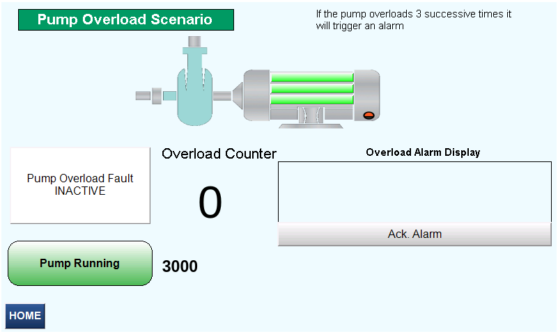
After the “Pump Overload Fault” button is pressed 3 successive times it will trigger the Alarm Counters User Interface Overload Active
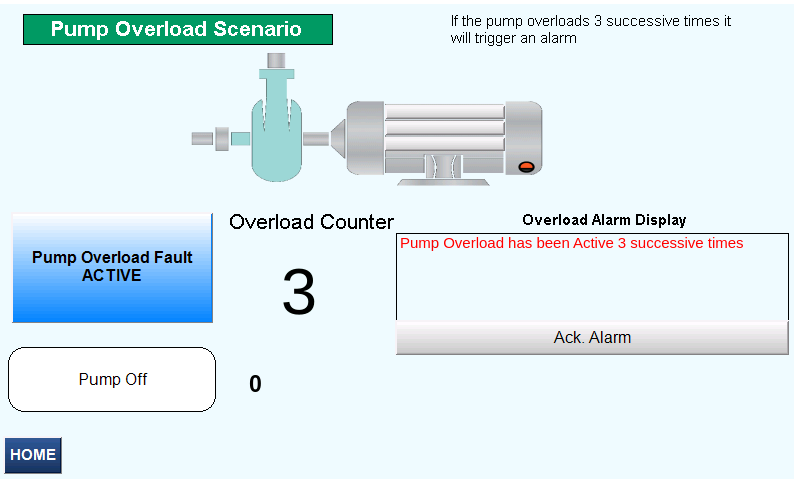
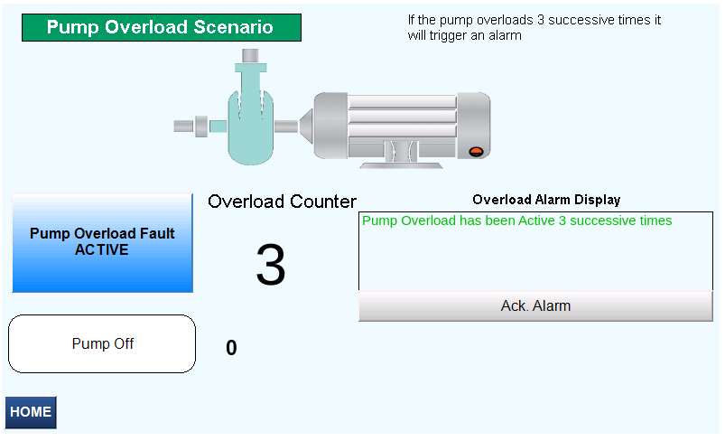
The “Pump Overload has been Active 3 successive times” alarm is acknowledged User Interface Counters Overload Alarm Active
The “Pump Running” button is pressed. After 3 seconds the alarm is cleared Counters User Interface Pump Running
Software Code (Compressor Preventative Maintenance)
Ladder Diagram
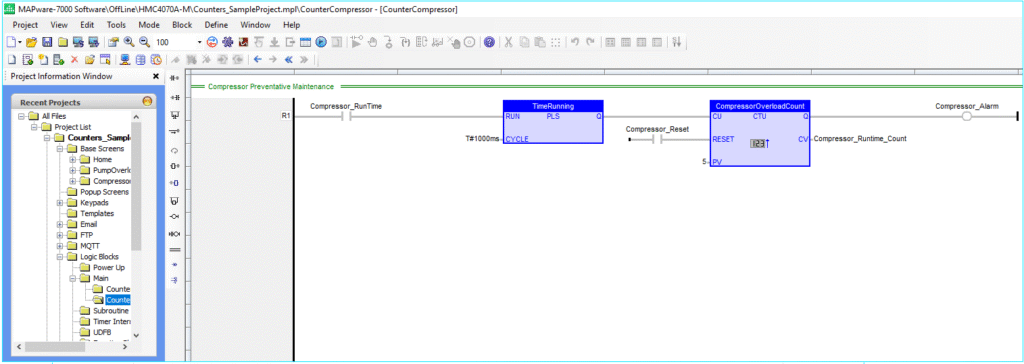
Rung 1: Turn the “Compressor_RunTime” bit ON to go through a Pulse Signal Generator Function. This function will pulse every 1 second representing 10 hours. When the timer gets to 5 seconds (or 50 hours), through an Up Counter function, it will trigger the “Compressor_Alarm”. Acknowledge the alarm, Then manually hit the “ResetCompressor” button to clear the alarm.
Structured text
Another type of IEC Language you can use:
TimeRunning ( Compressor_RunTime, T#1000ms );
CompressorOverloadCount ( TimeRunning.Q, Compressor_Reset, 5 );
Compressor_Runtime_Count := CompressorOverloadCount.CV;
Compressor_Alarm := CompressorOverloadCount.Q;
User Interface (Compressor Preventative Maintenance)
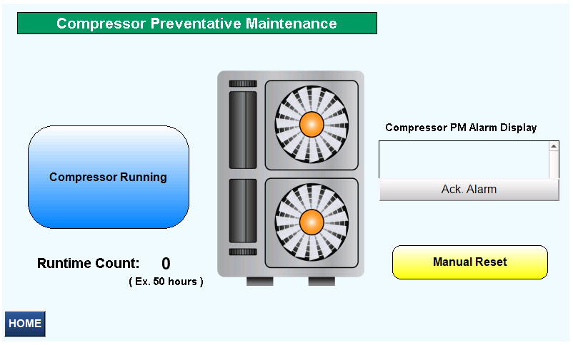
After the “Compressor Running” button is turned ON and the “Runtime Count” gets to 5 (50 hours), it will trigger an alarm. Counters User Interface Preventative Maintenance Compressor Running
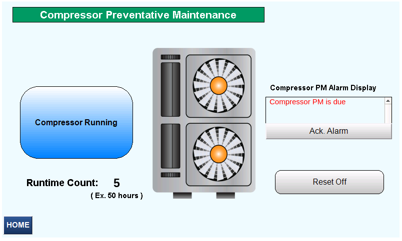
The “Compressor PM is due” alarm is acknowledged User Interface Counters Preventative Maintenance PM Due Alarm
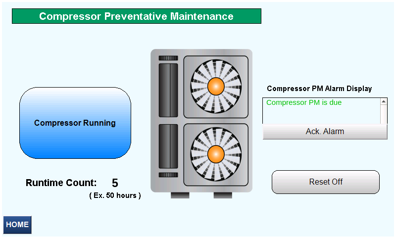
The “Manual Reset” button is pressed and the alarm is cleared User Interface Counters Preventative Maintenance Manual Reset
Sample Project
The project shown above was designed for the specific hardware mentioned at the beginning of the tutorial and is intended to provide you guidance when programming your unit. If you are using models other than the ones specified in this sample project, similar steps can be duplicated within your own project.
Download MAPware Sample Project
Resources & Documentation
HMC/MAPware-7000 Resources
MAPware-7000 Getting Started Guide
MAPware-7000 Programming Manual
IEC 61131-3 Programming Guide for MAPware-7000
HMC3 I/O Module Guide
More
See our Support Center for a complete list of Quick Start and Installation Guides
About the Author
